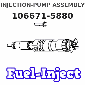
Information injection-pump assembly
BOSCH
9 400 616 885
9400616885
ZEXEL
106671-5880
1066715880
NISSAN-DIESEL
1671496512
1671496512
Rating:
Service parts 106671-5880 INJECTION-PUMP ASSEMBLY:
1.
_
7.
COUPLING PLATE
8.
_
9.
_
11.
Nozzle and Holder
16600-96520
12.
Open Pre:MPa(Kqf/cm2)
22.6{230}

15.
NOZZLE SET
Include in #1:
106671-5880
as INJECTION-PUMP ASSEMBLY
Cross reference number
BOSCH
9 400 616 885
9400616885
ZEXEL
106671-5880
1066715880
NISSAN-DIESEL
1671496512
1671496512
Zexel num
Bosch num
Firm num
Name
106671-5880
9 400 616 885
1671496512 NISSAN-DIESEL
INJECTION-PUMP ASSEMBLY
PE6T K
PE6T K
Calibration Data:
Adjustment conditions
Test oil
1404 Test oil ISO4113 or {SAEJ967d}
1404 Test oil ISO4113 or {SAEJ967d}
Test oil temperature
degC
40
40
45
Nozzle and nozzle holder
105780-8140
Bosch type code
EF8511/9A
Nozzle
105780-0000
Bosch type code
DN12SD12T
Nozzle holder
105780-2080
Bosch type code
EF8511/9
Opening pressure
MPa
17.2
Opening pressure
kgf/cm2
175
Injection pipe
Outer diameter - inner diameter - length (mm) mm 8-3-600
Outer diameter - inner diameter - length (mm) mm 8-3-600
Overflow valve
132424-0620
Overflow valve opening pressure
kPa
157
123
191
Overflow valve opening pressure
kgf/cm2
1.6
1.25
1.95
Tester oil delivery pressure
kPa
157
157
157
Tester oil delivery pressure
kgf/cm2
1.6
1.6
1.6
Direction of rotation (viewed from drive side)
Right R
Right R
Injection timing adjustment
Direction of rotation (viewed from drive side)
Right R
Right R
Injection order
1-4-2-6-
3-5
Pre-stroke
mm
3.65
3.6
3.7
Beginning of injection position
Drive side NO.1
Drive side NO.1
Difference between angles 1
Cal 1-4 deg. 60 59.5 60.5
Cal 1-4 deg. 60 59.5 60.5
Difference between angles 2
Cyl.1-2 deg. 120 119.5 120.5
Cyl.1-2 deg. 120 119.5 120.5
Difference between angles 3
Cal 1-6 deg. 180 179.5 180.5
Cal 1-6 deg. 180 179.5 180.5
Difference between angles 4
Cal 1-3 deg. 240 239.5 240.5
Cal 1-3 deg. 240 239.5 240.5
Difference between angles 5
Cal 1-5 deg. 300 299.5 300.5
Cal 1-5 deg. 300 299.5 300.5
Injection quantity adjustment
Adjusting point
A
Rack position
11.7
Pump speed
r/min
650
650
650
Average injection quantity
mm3/st.
157
155
159
Max. variation between cylinders
%
0
-4
4
Basic
*
Fixing the lever
*
Boost pressure
kPa
66.7
66.7
Boost pressure
mmHg
500
500
Injection quantity adjustment_02
Adjusting point
C
Rack position
8.1+-0.5
Pump speed
r/min
250
250
250
Average injection quantity
mm3/st.
15
14
16
Max. variation between cylinders
%
0
-10
10
Fixing the rack
*
Boost pressure
kPa
0
0
0
Boost pressure
mmHg
0
0
0
Boost compensator adjustment
Pump speed
r/min
400
400
400
Rack position
R1(9.5)
Boost pressure
kPa
17.3
17.3
17.3
Boost pressure
mmHg
130
130
130
Boost compensator adjustment_02
Pump speed
r/min
400
400
400
Rack position
R1+1.6
Boost pressure
kPa
37.3
36
38.6
Boost pressure
mmHg
280
270
290
Boost compensator adjustment_03
Pump speed
r/min
400
400
400
Rack position
12.2+0.2
Boost pressure
kPa
53.3
53.3
53.3
Boost pressure
mmHg
400
400
400
Timer adjustment
Pump speed
r/min
1155++
Advance angle
deg.
0
0
0
Remarks
Do not advance until starting N = 1155.
Do not advance until starting N = 1155.
Timer adjustment_02
Pump speed
r/min
1155
Advance angle
deg.
0.5
Timer adjustment_03
Pump speed
r/min
-
Advance angle
deg.
2
2
2
Remarks
Measure the actual speed, stop
Measure the actual speed, stop
Test data Ex:
Governor adjustment
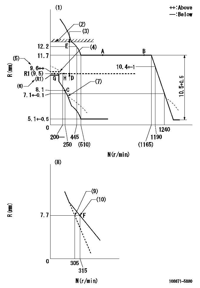
N:Pump speed
R:Rack position (mm)
(1)Tolerance for racks not indicated: +-0.05mm.
(2)Rack limit using the stop lever: R1
(3)Boost compensator stroke: BCL
(4)Protrusion is possible.
(5)At full boost
(6)At 0 boost.
(7)Damper spring setting: DL
(8)Variable speed specification: idling adjustment
(9)Main spring setting
(10)Set idle sub-spring
----------
R1=12.2+0.2mm BCL=(2.8)mm DL=6.5-0.2mm
----------
----------
R1=12.2+0.2mm BCL=(2.8)mm DL=6.5-0.2mm
----------
Speed control lever angle
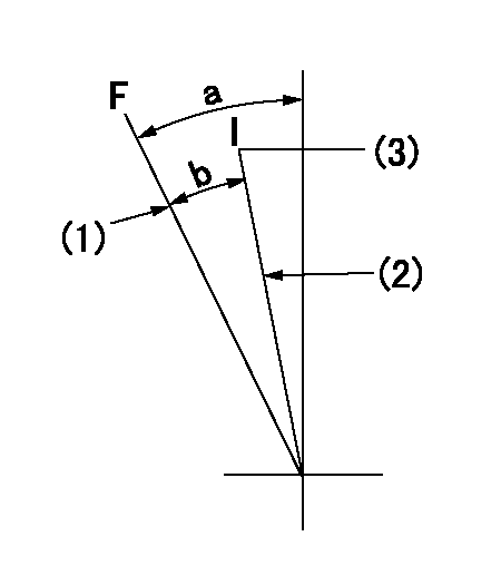
F:Full speed
I:Idle
(1)Stopper bolt setting
(2)Stopper bolt setting
(3)Set the pump speed at aa
----------
aa=315r/min
----------
a=(24.5deg)+-5deg b=(16.5deg)+-5deg
----------
aa=315r/min
----------
a=(24.5deg)+-5deg b=(16.5deg)+-5deg
0000000901
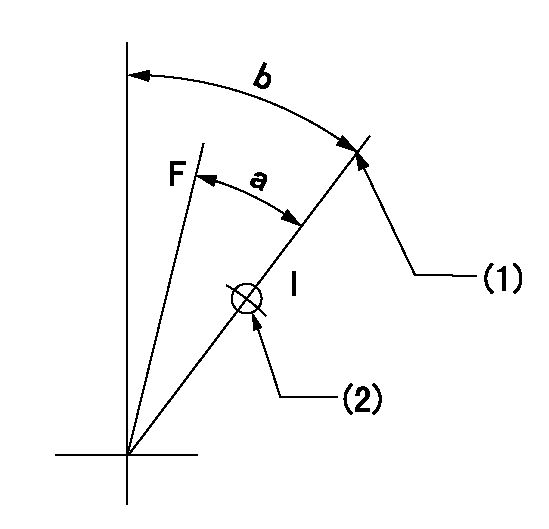
F:Full load
I:Idle
(1)Stopper bolt setting
(2)Use the hole at R = aa
----------
aa=41mm
----------
a=25deg+-3deg b=36.5deg+-5deg
----------
aa=41mm
----------
a=25deg+-3deg b=36.5deg+-5deg
Stop lever angle
N:Pump normal
S:Stop the pump.
(1)Rack position = aa
(2)Use the pin at R = bb
----------
aa=12.2+0.2mm bb=45mm
----------
a=41deg+-5deg b=37.5deg+-5deg
----------
aa=12.2+0.2mm bb=45mm
----------
a=41deg+-5deg b=37.5deg+-5deg
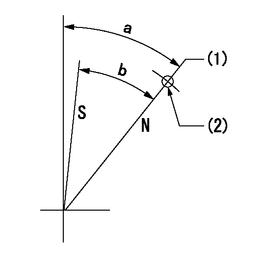
Timing setting

(1)Pump vertical direction
(2)Coupling's key groove position at No 1 cylinder's beginning of injection
(3)-
(4)-
----------
----------
a=(30deg)
----------
----------
a=(30deg)
Information:
Exhaust Smoke Can Be Seen While Starting
Possible Causes/Corrections Cold Outside TemperaturesIt may be necessary to use starting aids, or to heat engine oil or coolant at temperatures below -12°C (10°F). Air In Fuel SystemWith air in the fuel system, the engine will normally be difficult to start, run rough, and release a large amount of white smoke. If the engine will not start, loosen a fuel injection line nut at the through the head adapter and crank the engine until fuel comes out. Tighten the fuel line nut. Start the engine. If the engine still does not run smooth or releases a large amount of white smoke, loosen the fuel line nuts one at a time at the through the head adapters until the fuel that comes out is free of air. Tighten the fuel line nuts. If the air can not be removed in this way, put 35 kPa (5 psi) of air pressure to the fuel tank.
Do not use more than 55 kPa (8 psi) of air pressure in the fuel tank or damage to the tank may result.
Check for leakage at the connections between the fuel tank and the fuel transfer pump. If leaks are found, tighten the connections or replace the lines. It there are no visual leaks, remove the fuel supply line from the tank and connect it to an outside fuel supply. If this corrects the problem, the suction line (standpipe) inside the fuel tank has a leak. Low Quality FuelRemove a small amount of fuel from the tank and check for water in the fuel. If there is water in the fuel, remove fuel from the tank until it is free of water and fill with a good quality fuel. For more information refer to SEBD0717, Diesel Fuels And Your Engine.Change the fuel filter and "prime" (remove the air and/or low quality fuel from the fuel system) the fuel system with the fuel priming pump. If there is no water in the fuel, prime and start the engine by using an outside source of fuel. If engine starts correctly using different fuel, remove all fuel from the tank and fill with good quality fuel. Prime the fuel system if necessary. Low Fuel PressureChange the primary and secondary fuel filters and check to make sure the fuel lines are not plugged or damaged. If the filters or lines are not the cause, a repair or replacement of the fuel transfer pump is needed. Fuel Injection Timing Not CorrectCheck and make necessary adjustments as in Testing and Adjusting Section of this Service Manual. Valve Adjustment Not CorrectCheck and make necessary adjustments as in Testing and Adjusting Section of this Service Manual. Intake valve lash is 0.38 mm (.015 in) and exhaust valve lash is 0.64 mm (.025 in). Defective Fuel Nozzle(s)Remove the fuel nozzles and test as in Testing and Adjusting Section of this Service Manual. Low CompressionSee "Misfiring and Running Rough".Exhaust Smoke Cannot Be Seen While Starting
Possible Causes/Corrections No Fuel In Tank(s)Check
Have questions with 106671-5880?
Group cross 106671-5880 ZEXEL
Nissan-Diesel
Nissan-Diesel
106671-5880
9 400 616 885
1671496512
INJECTION-PUMP ASSEMBLY
PE6T
PE6T