Information injection-pump assembly
BOSCH
9 400 616 884
9400616884
ZEXEL
106671-5870
1066715870
NISSAN-DIESEL
1671296512
1671296512

Rating:
Service parts 106671-5870 INJECTION-PUMP ASSEMBLY:
1.
_
7.
COUPLING PLATE
8.
_
9.
_
11.
Nozzle and Holder
16600-96609
12.
Open Pre:MPa(Kqf/cm2)
17.7{180}/22.6{230}
15.
NOZZLE SET
Include in #1:
106671-5870
as INJECTION-PUMP ASSEMBLY
Cross reference number
BOSCH
9 400 616 884
9400616884
ZEXEL
106671-5870
1066715870
NISSAN-DIESEL
1671296512
1671296512
Zexel num
Bosch num
Firm num
Name
106671-5870
9 400 616 884
1671296512 NISSAN-DIESEL
INJECTION-PUMP ASSEMBLY
PF6TA K 14CA INJECTION PUMP ASSY PE6P,6PD PE
PF6TA K 14CA INJECTION PUMP ASSY PE6P,6PD PE
Calibration Data:
Adjustment conditions
Test oil
1404 Test oil ISO4113 or {SAEJ967d}
1404 Test oil ISO4113 or {SAEJ967d}
Test oil temperature
degC
40
40
45
Nozzle and nozzle holder
105780-8140
Bosch type code
EF8511/9A
Nozzle
105780-0000
Bosch type code
DN12SD12T
Nozzle holder
105780-2080
Bosch type code
EF8511/9
Opening pressure
MPa
17.2
Opening pressure
kgf/cm2
175
Injection pipe
Outer diameter - inner diameter - length (mm) mm 8-3-600
Outer diameter - inner diameter - length (mm) mm 8-3-600
Overflow valve
134424-0020
Overflow valve opening pressure
kPa
157
157
157
Overflow valve opening pressure
kgf/cm2
1.6
1.6
1.6
Tester oil delivery pressure
kPa
157
157
157
Tester oil delivery pressure
kgf/cm2
1.6
1.6
1.6
Direction of rotation (viewed from drive side)
Right R
Right R
Injection timing adjustment
Direction of rotation (viewed from drive side)
Right R
Right R
Injection order
1-4-2-6-
3-5
Pre-stroke
mm
3.9
3.85
3.95
Beginning of injection position
Drive side NO.1
Drive side NO.1
Difference between angles 1
Cal 1-4 deg. 60 59.5 60.5
Cal 1-4 deg. 60 59.5 60.5
Difference between angles 2
Cyl.1-2 deg. 120 119.5 120.5
Cyl.1-2 deg. 120 119.5 120.5
Difference between angles 3
Cal 1-6 deg. 180 179.5 180.5
Cal 1-6 deg. 180 179.5 180.5
Difference between angles 4
Cal 1-3 deg. 240 239.5 240.5
Cal 1-3 deg. 240 239.5 240.5
Difference between angles 5
Cal 1-5 deg. 300 299.5 300.5
Cal 1-5 deg. 300 299.5 300.5
Injection quantity adjustment
Adjusting point
A
Rack position
11.6
Pump speed
r/min
750
750
750
Average injection quantity
mm3/st.
197.5
195.5
199.5
Max. variation between cylinders
%
0
-4
4
Basic
*
Fixing the lever
*
Injection quantity adjustment_02
Adjusting point
C
Rack position
6.2+-0.5
Pump speed
r/min
300
300
300
Average injection quantity
mm3/st.
11.5
10.5
12.5
Max. variation between cylinders
%
0
-10
10
Fixing the rack
*
Injection quantity adjustment_03
Adjusting point
D
Rack position
-
Pump speed
r/min
100
100
100
Average injection quantity
mm3/st.
185
185
205
Fixing the lever
*
Rack limit
*
Timer adjustment
Pump speed
r/min
-
Advance angle
deg.
0
0
0
Remarks
Measure speed (beginning of operation).
Measure speed (beginning of operation).
Timer adjustment_02
Pump speed
r/min
-
Advance angle
deg.
2
1.5
2.5
Remarks
Measure the actual speed, stop
Measure the actual speed, stop
Test data Ex:
Governor adjustment
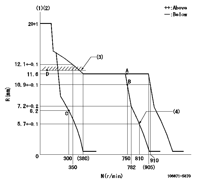
N:Pump speed
R:Rack position (mm)
(1)Target notch: K
(2)Tolerance for racks not indicated: +-0.05mm.
(3)RACK LIMIT
(4)Set idle sub-spring
----------
K=10
----------
----------
K=10
----------
Speed control lever angle
F:Full speed
I:Idle
(1)Set the pump speed at aa. ( At delivery )
(2)Stopper bolt setting
(3)Stopper bolt setting
(4)When pump speed set at bb
----------
aa=910r/min bb=750r/min
----------
a=5deg+-5deg b=25deg+-5deg c=7deg+-5deg
----------
aa=910r/min bb=750r/min
----------
a=5deg+-5deg b=25deg+-5deg c=7deg+-5deg
Stop lever angle

N:Pump normal
S:Stop the pump.
----------
----------
a=26.5deg+-5deg b=53deg+-5deg
----------
----------
a=26.5deg+-5deg b=53deg+-5deg
0000001501 GOV FULL LOAD ADJUSTMENT
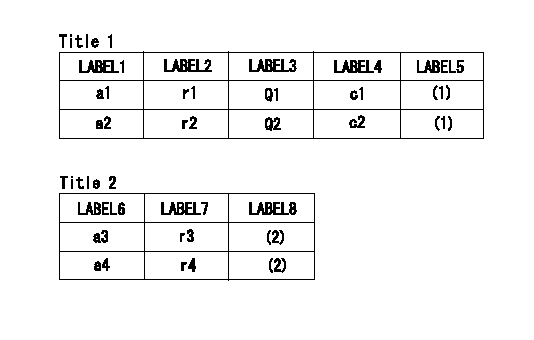
Title1:Full load stopper adjustment
Title2:Governor set speed
LABEL1:Distinguishing
LABEL2:Pump speed (r/min)
LABEL3:Ave. injection quantity (mm3/st)
LABEL4:Max. var. bet. cyl.
LABEL5:Remarks
LABEL6:Distinguishing
LABEL7:Governor set speed (r/min)
LABEL8:Remarks
(1)Adjustment conditions are the same as those for measuring injection quantity.
(2)-
----------
----------
a1=A a2=- r1=750r/min r2=- Q1=197.5+-2mm3/st Q2=- c1=+-4% c2=- a3=18 a4=15 r3=900r/min r4=750r/min
----------
----------
a1=A a2=- r1=750r/min r2=- Q1=197.5+-2mm3/st Q2=- c1=+-4% c2=- a3=18 a4=15 r3=900r/min r4=750r/min
Timing setting

(1)Pump vertical direction
(2)Coupling's key groove position at No 1 cylinder's beginning of injection
(3)-
(4)-
----------
----------
a=(20deg)
----------
----------
a=(20deg)
Information:
White Smoke
Possible Causes/Corrections Cold Outside TemperaturesWhen the air outside is cold, the cylinder temperature is cooler. Not all the fuel will burn in the cylinders. The fuel which does not burn comes out the exhaust as white smoke. White smoke is normal in cold temperatures until the engine operates long enough to become warm. There will be less white smoke if No. 1 diesel fuel is used. Intake Manifold Heater Not WorkingIf dash light goes out before 60 seconds or is blinking refer to Troubleshooting in Special Instruction, SEHS9773, Installing the 1047618 Intake Manifold Heater. Long Idle PeriodsWhen an engine runs at idle speed for a long period of time, the cylinders cool and all of the fuel does not burn. Do not idle an engine for a long period of time. Stop an engine when it is not in use. If long idle periods are necessary, use No. 1 diesel fuel. Engine Operating Temperature Too LowThis can cause white smoke on startup. If the smoke is slow to clear from the exhaust, check and make a replacement of the thermostat if needed. Low Quality FuelTest the engine using fuel according to recommendations by Caterpillar Inc. For more information refer to SEBD0717, Diesel Fuels And Your Engine. Air In Fuel SystemWith air in the fuel system, the engine will normally be difficult to start, run rough, and release a large amount of white smoke. If the engine will not start, loosen a fuel injection line nut at the through the head adapter and crank the engine until fuel comes out. Tighten the fuel line nut. Start the engine. If the engine still does not run smooth or releases a large amount of white smoke, loosen the fuel line nuts one at a time at the through head adapters until the fuel that comes out is free of air. Tighten the fuel line nuts. If the air cannot be removed in this way, put 35 kPa (5 psi) of air pressure to the fuel tank.
Do not use more than 55 kPa (8 psi) of air pressure in the fuel tank or damage to the tank may result.
Check for leakage at the connections between the fuel tank and the fuel transfer pump. If leaks are found, tighten the connections or replace the lines. If there are no visual leaks, remove the fuel supply line from the tank and connect it to an outside fuel supply. If this corrects the problem, the suction line (standpipe) inside the fuel tank has a leak. Fuel Injection Timing Not CorrectCheck and make necessary adjustments as in Testing and Adjusting Section of this Service Manual. Valve Adjustment Not CorrectCheck and make necessary adjustments as in Testing and Adjusting Section of this Service Manual. Intake valve lash is 0.38 mm (.015 in) and exhaust valve lash is 0.64 mm (.025 in). Defective Fuel Nozzle(s)Defective fuel nozzles will normally cause the engine to "misfire" and run rough, but can cause too much smoke with the engine still
Have questions with 106671-5870?
Group cross 106671-5870 ZEXEL
Nissan-Diesel
Nissan-Diesel
106671-5870
9 400 616 884
1671296512
INJECTION-PUMP ASSEMBLY
PF6TA
PF6TA