Information injection-pump assembly
BOSCH
9 400 612 539
9400612539
ZEXEL
106671-5860
1066715860
NISSAN-DIESEL
1671496511
1671496511
Rating:
Service parts 106671-5860 INJECTION-PUMP ASSEMBLY:
1.
_
7.
COUPLING PLATE
8.
_
9.
_
11.
Nozzle and Holder
16600-96614
12.
Open Pre:MPa(Kqf/cm2)
17.7{180}/22.6{230}
14.
NOZZLE
Include in #1:
106671-5860
as INJECTION-PUMP ASSEMBLY
Cross reference number
BOSCH
9 400 612 539
9400612539
ZEXEL
106671-5860
1066715860
NISSAN-DIESEL
1671496511
1671496511
Zexel num
Bosch num
Firm num
Name
106671-5860
9 400 612 539
1671496511 NISSAN-DIESEL
INJECTION-PUMP ASSEMBLY
PF6HT K 14CA INJECTION PUMP ASSY PE6P,6PD PE
PF6HT K 14CA INJECTION PUMP ASSY PE6P,6PD PE
Calibration Data:
Adjustment conditions
Test oil
1404 Test oil ISO4113 or {SAEJ967d}
1404 Test oil ISO4113 or {SAEJ967d}
Test oil temperature
degC
40
40
45
Nozzle and nozzle holder
105780-8140
Bosch type code
EF8511/9A
Nozzle
15780-0000
Bosch type code
DN12SD12T
Nozzle holder
105780-2080
Bosch type code
EF8511/9
Opening pressure
MPa
17.2
Opening pressure
kgf/cm2
175
Injection pipe
Outer diameter - inner diameter - length (mm) mm 8-3-600
Outer diameter - inner diameter - length (mm) mm 8-3-600
Overflow valve
134424-0020
Overflow valve opening pressure
kPa
157
157
157
Overflow valve opening pressure
kgf/cm2
1.6
1.6
1.6
Tester oil delivery pressure
kPa
157
157
157
Tester oil delivery pressure
kgf/cm2
1.6
1.6
1.6
Direction of rotation (viewed from drive side)
Right R
Right R
Injection timing adjustment
Direction of rotation (viewed from drive side)
Right R
Right R
Injection order
1-4-2-6-
3-5
Pre-stroke
mm
3.9
3.85
3.95
Beginning of injection position
Drive side NO.1
Drive side NO.1
Difference between angles 1
Cal 1-4 deg. 60 59.5 60.5
Cal 1-4 deg. 60 59.5 60.5
Difference between angles 2
Cyl.1-2 deg. 120 119.5 120.5
Cyl.1-2 deg. 120 119.5 120.5
Difference between angles 3
Cal 1-6 deg. 180 179.5 180.5
Cal 1-6 deg. 180 179.5 180.5
Difference between angles 4
Cal 1-3 deg. 240 239.5 240.5
Cal 1-3 deg. 240 239.5 240.5
Difference between angles 5
Cal 1-5 deg. 300 299.5 300.5
Cal 1-5 deg. 300 299.5 300.5
Injection quantity adjustment
Adjusting point
A
Rack position
11.2
Pump speed
r/min
1050
1050
1050
Average injection quantity
mm3/st.
156
154
158
Max. variation between cylinders
%
0
-4
4
Basic
*
Fixing the lever
*
Boost pressure
kPa
72
72
Boost pressure
mmHg
540
540
Injection quantity adjustment_02
Adjusting point
C
Rack position
6.3+-0.5
Pump speed
r/min
325
325
325
Average injection quantity
mm3/st.
14
13
15
Max. variation between cylinders
%
0
-10
10
Fixing the rack
*
Boost pressure
kPa
0
0
0
Boost pressure
mmHg
0
0
0
Boost compensator adjustment
Pump speed
r/min
300
300
300
Rack position
9.6
Boost pressure
kPa
8
8
8
Boost pressure
mmHg
60
60
60
Boost compensator adjustment_02
Pump speed
r/min
300
300
300
Rack position
11.2
Boost pressure
kPa
26.7
24
29.4
Boost pressure
mmHg
200
180
220
Boost compensator adjustment_03
Pump speed
r/min
300
300
300
Rack position
(13.4)
Boost pressure
kPa
58.7
58.7
58.7
Boost pressure
mmHg
440
440
440
Timer adjustment
Pump speed
r/min
750--
Advance angle
deg.
0
0
0
Remarks
Start
Start
Timer adjustment_02
Pump speed
r/min
700
Advance angle
deg.
0.5
Timer adjustment_03
Pump speed
r/min
1020
Advance angle
deg.
2
1.5
2.5
Remarks
Finish
Finish
Test data Ex:
Governor adjustment
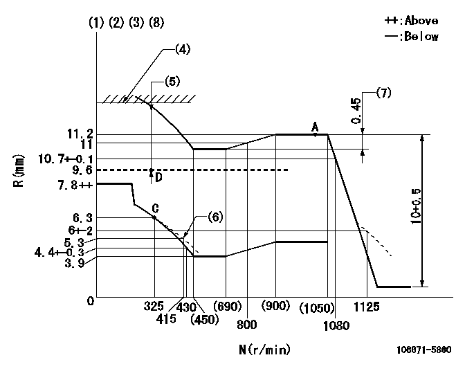
N:Pump speed
R:Rack position (mm)
(1)Lever ratio: RT
(2)Target shim dimension: TH
(3)Tolerance for racks not indicated: +-0.05mm.
(4)Rack limit using stop lever: R1 (at N = N1)
(5)Boost compensator stroke: BCL
(6)Damper spring setting
(7)Rack difference between N = N2 and N = N3
(8)Perform governor adjustment at an ambient temperature of at least 15 deg C (boost compensator start spring is shape memory alloy).
----------
RT=1 TH=1.7mm R1=13.5+-0.1mm N1=100r/min BCL=(3.8)mm N2=1050r/min N3=650r/min
----------
----------
RT=1 TH=1.7mm R1=13.5+-0.1mm N1=100r/min BCL=(3.8)mm N2=1050r/min N3=650r/min
----------
Speed control lever angle

F:Full speed
----------
----------
a=(9deg)+-5deg
----------
----------
a=(9deg)+-5deg
0000000901
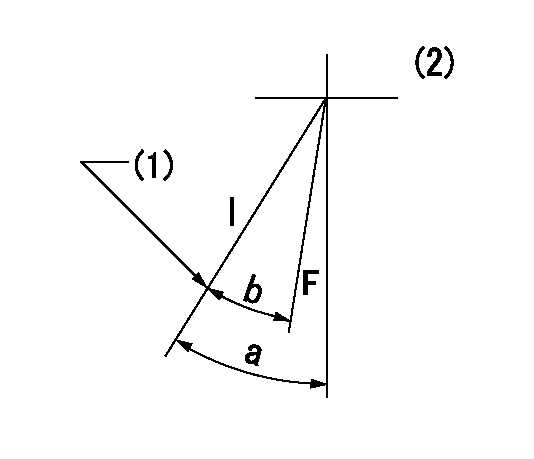
F:Full load
I:Idle
(1)Stopper bolt setting
(2)(at R = aa)
----------
aa=25.5mm
----------
a=33deg+-5deg b=25.5deg+-3deg
----------
aa=25.5mm
----------
a=33deg+-5deg b=25.5deg+-3deg
Stop lever angle
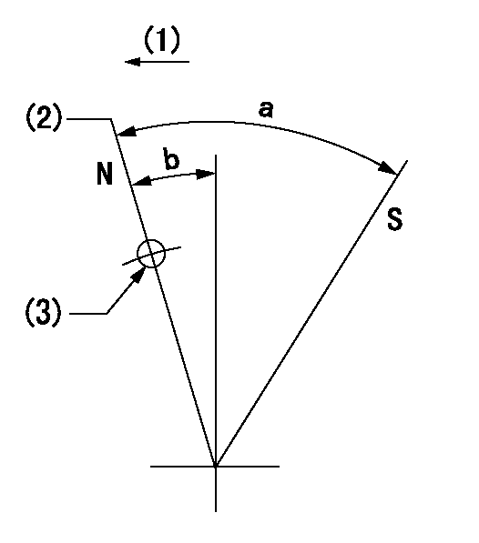
N:Pump normal
S:Stop the pump.
(1)Drive side
(2)Rack position = aa
(3)Use the hole at R = bb
----------
aa=13.5+-0.1mm bb=32mm
----------
a=35deg+-5deg b=9.5deg+-5deg
----------
aa=13.5+-0.1mm bb=32mm
----------
a=35deg+-5deg b=9.5deg+-5deg
Timing setting

(1)Pump vertical direction
(2)Coupling's key groove position at No 1 cylinder's beginning of injection
(3)-
(4)-
----------
----------
a=(20deg)
----------
----------
a=(20deg)
Information:
Engine Runs Smoothly
Possible Causes/Corrections Dirty Air CleanerIf the air cleaner has a restriction indicator, see if the red piston is in view. If there is no restriction indicator, restriction can be checked with a water manometer or a vacuum gauge (which measures in inches of water). Make a connection to the piping between the air cleaner and the inlet of the turbocharger. Check with the engine running at full load rpm. Maximum restriction is 635 mm (25 in) of water. If a gauge is not available, visually check the air cleaner element for dirt. If the element is dirty, clean the element or install a new element. Air Inlet Piping Damage Or RestrictionMake a visual inspection of the air inlet system and check for damage to piping, rags in the inlet piping, or damage to the rain cap or the cap pushed too far on the inlet pipe. If no damage is seen, check inlet restriction with a clean air cleaner element. Exhaust System RestrictionMake a visual inspection of the exhaust system. Check for damage to piping or for a defective muffler. If no damage is found, you can check the system by checking the back pressure from the exhaust (pressure difference measurement between exhaust outlet and atmosphere). The back pressure must not be more than 1016 mm (40 in) of water. You can also check by removing the exhaust pipes from the exhaust manifolds. With the exhaust pipes removed, start and load the engine on a chassis dynamometer to see if the problem is corrected. Fuel Injection Timing Not CorrectCheck timing with the 8T5300 Timing Indicator Group. Make necessary adjustments as in Testing and Adjusting Section of this Service Manual. Fuel Setting Is Not CorrectCheck and make necessary adjustments as in Testing and Adjusting Section of this Service Manual. See the Fuel Setting And Related Information Fiche for the correct fuel setting. Low Quality FuelTest the engine with fuel according to recommendations by Caterpillar Inc. For more information refer to SEBD0717, Diesel Fuels And Your Engine. Also, Special Instruction, SEHS6947 has fuel correction factors and tables. Defective Fuel Nozzle(s)Defective fuel nozzles will normally cause the engine to misfire and run rough, but can cause too much smoke with engine still running smooth. Remove the fuel nozzles and test as in Testing and Adjusting Section of this Service Manual. Wrong Seal Washer Installed Under Nozzle(s)The use of incorrect washers change the location of the fuel injection nozzles in the combustion chamber. This effects smoke. Check the Engine Arrangement for the correct part number to use. Valve Adjustment Not Correct Or Valve LeakageCheck and make necessary adjustments as in Testing and Adjusting Section of this Service Manual. Intake valve lash is 0.38 mm (.015 in) and exhaust valve lash is 0.64 mm (.025 in). Valve leakage normally causes the engine to misfire and run rough. Defective Fuel Injection PumpAn injection pump can have a good fuel flow coming from it but cause rough running because of slow timing that
Possible Causes/Corrections Dirty Air CleanerIf the air cleaner has a restriction indicator, see if the red piston is in view. If there is no restriction indicator, restriction can be checked with a water manometer or a vacuum gauge (which measures in inches of water). Make a connection to the piping between the air cleaner and the inlet of the turbocharger. Check with the engine running at full load rpm. Maximum restriction is 635 mm (25 in) of water. If a gauge is not available, visually check the air cleaner element for dirt. If the element is dirty, clean the element or install a new element. Air Inlet Piping Damage Or RestrictionMake a visual inspection of the air inlet system and check for damage to piping, rags in the inlet piping, or damage to the rain cap or the cap pushed too far on the inlet pipe. If no damage is seen, check inlet restriction with a clean air cleaner element. Exhaust System RestrictionMake a visual inspection of the exhaust system. Check for damage to piping or for a defective muffler. If no damage is found, you can check the system by checking the back pressure from the exhaust (pressure difference measurement between exhaust outlet and atmosphere). The back pressure must not be more than 1016 mm (40 in) of water. You can also check by removing the exhaust pipes from the exhaust manifolds. With the exhaust pipes removed, start and load the engine on a chassis dynamometer to see if the problem is corrected. Fuel Injection Timing Not CorrectCheck timing with the 8T5300 Timing Indicator Group. Make necessary adjustments as in Testing and Adjusting Section of this Service Manual. Fuel Setting Is Not CorrectCheck and make necessary adjustments as in Testing and Adjusting Section of this Service Manual. See the Fuel Setting And Related Information Fiche for the correct fuel setting. Low Quality FuelTest the engine with fuel according to recommendations by Caterpillar Inc. For more information refer to SEBD0717, Diesel Fuels And Your Engine. Also, Special Instruction, SEHS6947 has fuel correction factors and tables. Defective Fuel Nozzle(s)Defective fuel nozzles will normally cause the engine to misfire and run rough, but can cause too much smoke with engine still running smooth. Remove the fuel nozzles and test as in Testing and Adjusting Section of this Service Manual. Wrong Seal Washer Installed Under Nozzle(s)The use of incorrect washers change the location of the fuel injection nozzles in the combustion chamber. This effects smoke. Check the Engine Arrangement for the correct part number to use. Valve Adjustment Not Correct Or Valve LeakageCheck and make necessary adjustments as in Testing and Adjusting Section of this Service Manual. Intake valve lash is 0.38 mm (.015 in) and exhaust valve lash is 0.64 mm (.025 in). Valve leakage normally causes the engine to misfire and run rough. Defective Fuel Injection PumpAn injection pump can have a good fuel flow coming from it but cause rough running because of slow timing that
Have questions with 106671-5860?
Group cross 106671-5860 ZEXEL
Nissan-Diesel
Nissan-Diesel
106671-5860
9 400 612 539
1671496511
INJECTION-PUMP ASSEMBLY
PF6HT
PF6HT