Information injection-pump assembly
BOSCH
9 400 616 881
9400616881
ZEXEL
106671-5810
1066715810
NISSAN-DIESEL
1671496505
1671496505

Rating:
Cross reference number
BOSCH
9 400 616 881
9400616881
ZEXEL
106671-5810
1066715810
NISSAN-DIESEL
1671496505
1671496505
Zexel num
Bosch num
Firm num
Name
106671-5810
9 400 616 881
1671496505 NISSAN-DIESEL
INJECTION-PUMP ASSEMBLY
PE6TD K
PE6TD K
Calibration Data:
Adjustment conditions
Test oil
1404 Test oil ISO4113 or {SAEJ967d}
1404 Test oil ISO4113 or {SAEJ967d}
Test oil temperature
degC
40
40
45
Nozzle and nozzle holder
105780-8140
Bosch type code
EF8511/9A
Nozzle
105780-0000
Bosch type code
DN12SD12T
Nozzle holder
105780-2080
Bosch type code
EF8511/9
Opening pressure
MPa
17.2
Opening pressure
kgf/cm2
175
Injection pipe
Outer diameter - inner diameter - length (mm) mm 8-3-600
Outer diameter - inner diameter - length (mm) mm 8-3-600
Overflow valve
132424-0620
Overflow valve opening pressure
kPa
157
123
191
Overflow valve opening pressure
kgf/cm2
1.6
1.25
1.95
Tester oil delivery pressure
kPa
157
157
157
Tester oil delivery pressure
kgf/cm2
1.6
1.6
1.6
Direction of rotation (viewed from drive side)
Right R
Right R
Injection timing adjustment
Direction of rotation (viewed from drive side)
Right R
Right R
Injection order
1-4-2-6-
3-5
Pre-stroke
mm
3.65
3.6
3.7
Beginning of injection position
Drive side NO.1
Drive side NO.1
Difference between angles 1
Cal 1-4 deg. 60 59.5 60.5
Cal 1-4 deg. 60 59.5 60.5
Difference between angles 2
Cyl.1-2 deg. 120 119.5 120.5
Cyl.1-2 deg. 120 119.5 120.5
Difference between angles 3
Cal 1-6 deg. 180 179.5 180.5
Cal 1-6 deg. 180 179.5 180.5
Difference between angles 4
Cal 1-3 deg. 240 239.5 240.5
Cal 1-3 deg. 240 239.5 240.5
Difference between angles 5
Cal 1-5 deg. 300 299.5 300.5
Cal 1-5 deg. 300 299.5 300.5
Injection quantity adjustment
Adjusting point
A
Rack position
11.4
Pump speed
r/min
650
650
650
Average injection quantity
mm3/st.
161
159
163
Max. variation between cylinders
%
0
-4
4
Basic
*
Fixing the lever
*
Boost pressure
kPa
85.3
85.3
Boost pressure
mmHg
640
640
Injection quantity adjustment_02
Adjusting point
C
Rack position
6.7+-0.5
Pump speed
r/min
270
270
270
Average injection quantity
mm3/st.
15.5
14.5
16.5
Max. variation between cylinders
%
0
-10
10
Fixing the rack
*
Boost pressure
kPa
0
0
0
Boost pressure
mmHg
0
0
0
Injection quantity adjustment_03
Adjusting point
D
Rack position
9.1
Pump speed
r/min
400
400
400
Average injection quantity
mm3/st.
96
93
99
Fixing the lever
*
Boost pressure
kPa
0
0
0
Boost pressure
mmHg
0
0
0
Boost compensator adjustment
Pump speed
r/min
350
350
350
Rack position
9.1
Boost pressure
kPa
16
14.7
17.3
Boost pressure
mmHg
120
110
130
Boost compensator adjustment_02
Pump speed
r/min
350
350
350
Rack position
9.9
Boost pressure
kPa
30
26
34
Boost pressure
mmHg
225
195
255
Boost compensator adjustment_03
Pump speed
r/min
350
350
350
Rack position
12.4+0.2
Boost pressure
kPa
72
72
72
Boost pressure
mmHg
540
540
540
Timer adjustment
Pump speed
r/min
875--
Advance angle
deg.
0
0
0
Remarks
Start
Start
Timer adjustment_02
Pump speed
r/min
825
Advance angle
deg.
0.5
Timer adjustment_03
Pump speed
r/min
925
Advance angle
deg.
1
0.5
1.5
Remarks
Finish
Finish
Test data Ex:
Governor adjustment
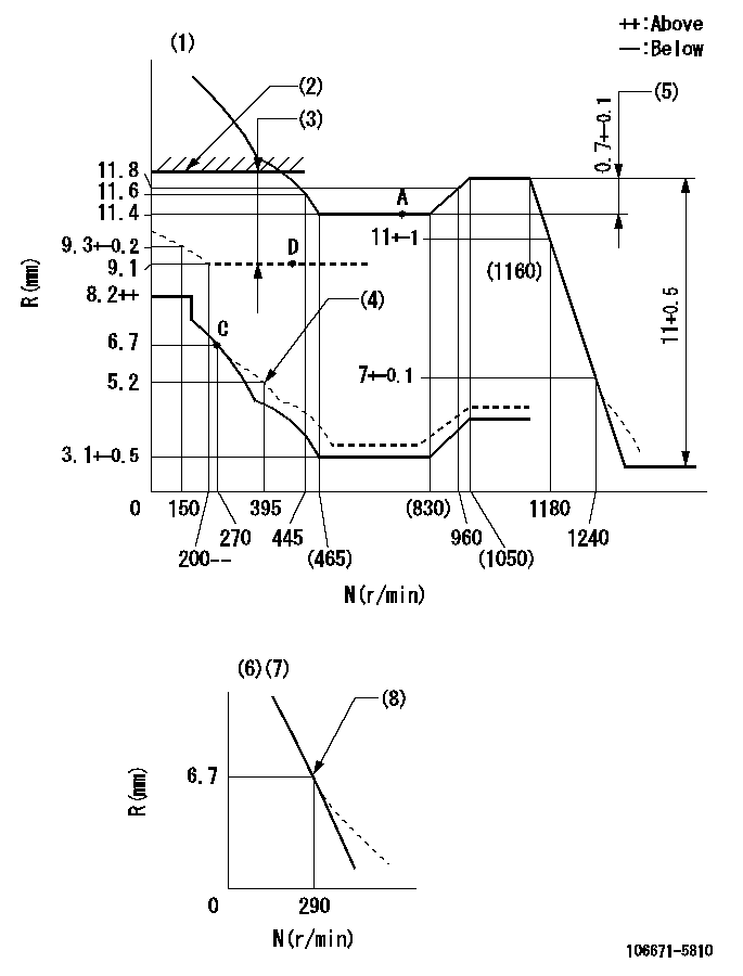
N:Pump speed
R:Rack position (mm)
(1)Tolerance for racks not indicated: +-0.05mm.
(2)Rack limit using stop lever: R1 (at N = N1)
(3)Boost compensator stroke: BCL
(4)Damper spring setting
(5)Rack difference between N = N2 and N = N3
(6)Variable speed specification: idling adjustment
(7)Fix the lever at the full-load position at delivery.
(8)Main spring setting
----------
R1=12.4+0.2mm N1=350r/min BCL=(3.4)mm N2=1100r/min N3=650r/min
----------
----------
R1=12.4+0.2mm N1=350r/min BCL=(3.4)mm N2=1100r/min N3=650r/min
----------
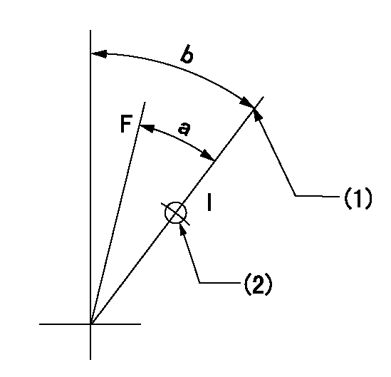
Speed control lever angle

F:Full speed
I:Idle
(1)Pump speed = aa
(2)Set the stopper bolt (fixed at full-load position at delivery.)
----------
aa=290r/min
----------
a=(16deg)+-5deg b=(7deg)+-5deg
----------
aa=290r/min
----------
a=(16deg)+-5deg b=(7deg)+-5deg
0000000901
F:Full load
I:Idle
(1)Stopper bolt setting
(2)Use the hole at R = aa
----------
aa=42mm
----------
a=30.5deg+-3deg b=45deg+-5deg
----------
aa=42mm
----------
a=30.5deg+-3deg b=45deg+-5deg
Stop lever angle
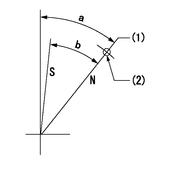
N:Pump normal
S:Stop the pump.
(1)Rack position = aa (at speed = bb)
(2)Use the pin above R = cc
----------
aa=12.4+0.2mm bb=350r/min cc=40mm
----------
a=41deg+-5deg b=41deg+-5deg
----------
aa=12.4+0.2mm bb=350r/min cc=40mm
----------
a=41deg+-5deg b=41deg+-5deg
0000001501 TAMPER PROOF
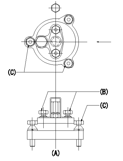
Tamperproofing-equipped boost compensator cover installation procedure
(A): figure shown by arrow
(B): after boost compensator adjustment, assemble and break off the screw head.
(C): specified torque
(1)Before adjusting the governor and the boost compensator, tighten the screw to the specified torque.
(Tightening torque T = T1 maximum)
(2)After adjusting the governor and the boost compensator, tighten to the specified torque to break off the bolt heads.
(Tightening torque T = T2)
----------
T1=2.5N-m(0.25kgf-m) T2=2.9~4.4N-m(0.3~0.45kgf-m)
----------
----------
T1=2.5N-m(0.25kgf-m) T2=2.9~4.4N-m(0.3~0.45kgf-m)
----------
Timing setting

(1)Pump vertical direction
(2)Coupling's key groove position at No 1 cylinder's beginning of injection
(3)-
(4)-
----------
----------
a=(25deg)
----------
----------
a=(25deg)
Information:
Low power and engine response complaints can be caused by very different reasons and require different repairs, but are often the same complaint from the operator. A discussion with the operator is needed to help correctly diagnose whether to repair for low power or slow response. At times, full engine horsepower is available, but the operator still complains of low power. Repairs for low power would not provide a satisfactory result, and may consume many hours with expensive repairs. The actual complaint may be the engines ability to respond to a changing load or shifting gears.Normally, engine power can be measured to determine if it is within specifications. When troubleshooting a "low horsepower" complaint, if fuel consumption, timing, speeds, and manifold pressure are within specification, do not spend additional time looking for "low engine horsepower". If it is still believed that performance of the vehicle is below that expected, look for horsepower losses in the transmission, differential, clutches, parasitic loads (fan, air compressor, air conditioner, etc), tires, low fuel density or high temperatures, but not the engine.Owner/Operator Input
The following are some of the questions which should be asked before beginning any diagnosis or repair for an engine performance complaint. There Are No Hard And Fast Answers For These Questions. There are many different truck engine specifications and truck vehicle specifications which will provide acceptable results. There are also a variety of customer expectations which are acceptable. The answers to these questions will give you a better understanding and perspective on the complaint and may identify characteristics which will help pinpoint the cause of the complaint quickly. 1. Is there a particular operating condition when the complaint occurs?Low power and response complaints require different repairs. Complaints during shifting will be different from complaints of low power in certain speed ranges or in certain terrains. 2. What are the customer's expectations for fuel mileage and power and why does he have those expectations?Comparisons to other trucks on the road often have many unseen variables. If comparison to others is the basis for the complaint, you must insure that the comparison is valid. 3. What are the normal upshift and downshift rpm's?If the shift points are too high, find out why. If the driver is operating this way out of habit or because he is taught to drive that way, arrange for him to receive the Caterpillar driver training information. If his shift points are too high because of poor performance, you may be able to correct this in the engine. 4. What are the normal routes and loads for the truck?You should be looking for the amount of city versus highway driving, versus mountainous, heavy versus light loads, and cold climate versus warm climate. 5. Can the operator detect a misfire?This can lead you to a diagnosis of just one cylinder rather than an entire engine system. 6. Does the engine smoke excessively, and if so, under what conditions?Excessive smoke can give indications about engine settings and engine internal conditions.
The following are some of the questions which should be asked before beginning any diagnosis or repair for an engine performance complaint. There Are No Hard And Fast Answers For These Questions. There are many different truck engine specifications and truck vehicle specifications which will provide acceptable results. There are also a variety of customer expectations which are acceptable. The answers to these questions will give you a better understanding and perspective on the complaint and may identify characteristics which will help pinpoint the cause of the complaint quickly. 1. Is there a particular operating condition when the complaint occurs?Low power and response complaints require different repairs. Complaints during shifting will be different from complaints of low power in certain speed ranges or in certain terrains. 2. What are the customer's expectations for fuel mileage and power and why does he have those expectations?Comparisons to other trucks on the road often have many unseen variables. If comparison to others is the basis for the complaint, you must insure that the comparison is valid. 3. What are the normal upshift and downshift rpm's?If the shift points are too high, find out why. If the driver is operating this way out of habit or because he is taught to drive that way, arrange for him to receive the Caterpillar driver training information. If his shift points are too high because of poor performance, you may be able to correct this in the engine. 4. What are the normal routes and loads for the truck?You should be looking for the amount of city versus highway driving, versus mountainous, heavy versus light loads, and cold climate versus warm climate. 5. Can the operator detect a misfire?This can lead you to a diagnosis of just one cylinder rather than an entire engine system. 6. Does the engine smoke excessively, and if so, under what conditions?Excessive smoke can give indications about engine settings and engine internal conditions.
Have questions with 106671-5810?
Group cross 106671-5810 ZEXEL
Nissan-Diesel
106671-5810
9 400 616 881
1671496505
INJECTION-PUMP ASSEMBLY
PE6TD
PE6TD