Information injection-pump assembly
BOSCH
9 400 616 880
9400616880
ZEXEL
106671-5800
1066715800
NISSAN-DIESEL
1671496504
1671496504
Rating:
Service parts 106671-5800 INJECTION-PUMP ASSEMBLY:
1.
_
7.
COUPLING PLATE
8.
_
9.
_
11.
Nozzle and Holder
16600-96520
12.
Open Pre:MPa(Kqf/cm2)
22.6{230}

15.
NOZZLE SET
Include in #1:
106671-5800
as INJECTION-PUMP ASSEMBLY
Cross reference number
BOSCH
9 400 616 880
9400616880
ZEXEL
106671-5800
1066715800
NISSAN-DIESEL
1671496504
1671496504
Zexel num
Bosch num
Firm num
Name
106671-5800
9 400 616 880
1671496504 NISSAN-DIESEL
INJECTION-PUMP ASSEMBLY
PE6T K 14CA INJECTION PUMP ASSY PE6P,6PD PE
PE6T K 14CA INJECTION PUMP ASSY PE6P,6PD PE
Calibration Data:
Adjustment conditions
Test oil
1404 Test oil ISO4113 or {SAEJ967d}
1404 Test oil ISO4113 or {SAEJ967d}
Test oil temperature
degC
40
40
45
Nozzle and nozzle holder
105780-8140
Bosch type code
EF8511/9A
Nozzle
105780-0000
Bosch type code
DN12SD12T
Nozzle holder
105780-2080
Bosch type code
EF8511/9
Opening pressure
MPa
17.2
Opening pressure
kgf/cm2
175
Injection pipe
Outer diameter - inner diameter - length (mm) mm 8-3-600
Outer diameter - inner diameter - length (mm) mm 8-3-600
Overflow valve
132424-0620
Overflow valve opening pressure
kPa
157
123
191
Overflow valve opening pressure
kgf/cm2
1.6
1.25
1.95
Tester oil delivery pressure
kPa
157
157
157
Tester oil delivery pressure
kgf/cm2
1.6
1.6
1.6
Direction of rotation (viewed from drive side)
Right R
Right R
Injection timing adjustment
Direction of rotation (viewed from drive side)
Right R
Right R
Injection order
1-4-2-6-
3-5
Pre-stroke
mm
3.65
3.6
3.7
Beginning of injection position
Drive side NO.1
Drive side NO.1
Difference between angles 1
Cal 1-4 deg. 60 59.5 60.5
Cal 1-4 deg. 60 59.5 60.5
Difference between angles 2
Cyl.1-2 deg. 120 119.5 120.5
Cyl.1-2 deg. 120 119.5 120.5
Difference between angles 3
Cal 1-6 deg. 180 179.5 180.5
Cal 1-6 deg. 180 179.5 180.5
Difference between angles 4
Cal 1-3 deg. 240 239.5 240.5
Cal 1-3 deg. 240 239.5 240.5
Difference between angles 5
Cal 1-5 deg. 300 299.5 300.5
Cal 1-5 deg. 300 299.5 300.5
Injection quantity adjustment
Adjusting point
A
Rack position
11.2
Pump speed
r/min
650
650
650
Average injection quantity
mm3/st.
155.5
153.5
157.5
Max. variation between cylinders
%
0
-4
4
Basic
*
Fixing the lever
*
Boost pressure
kPa
82.6
82.6
Boost pressure
mmHg
620
620
Injection quantity adjustment_02
Adjusting point
C
Rack position
6.7+-0.5
Pump speed
r/min
270
270
270
Average injection quantity
mm3/st.
15.5
14.5
16.5
Max. variation between cylinders
%
0
-10
10
Fixing the rack
*
Boost pressure
kPa
0
0
0
Boost pressure
mmHg
0
0
0
Injection quantity adjustment_03
Adjusting point
D
Rack position
9.7
Pump speed
r/min
400
400
400
Average injection quantity
mm3/st.
108
105
111
Fixing the lever
*
Boost pressure
kPa
0
0
0
Boost pressure
mmHg
0
0
0
Boost compensator adjustment
Pump speed
r/min
350
350
350
Rack position
9.7
Boost pressure
kPa
30
28.7
31.3
Boost pressure
mmHg
225
215
235
Boost compensator adjustment_02
Pump speed
r/min
350
350
350
Rack position
10.3
Boost pressure
kPa
40
36
44
Boost pressure
mmHg
300
270
330
Boost compensator adjustment_03
Pump speed
r/min
350
350
350
Rack position
11.8+0.2
Boost pressure
kPa
69.3
69.3
69.3
Boost pressure
mmHg
520
520
520
Timer adjustment
Pump speed
r/min
1150--
Advance angle
deg.
0
0
0
Remarks
Do not advance until N = 1150.
Do not advance until N = 1150.
Timer adjustment_02
Pump speed
r/min
1150
Advance angle
deg.
0.5
Timer adjustment_03
Pump speed
r/min
-
Advance angle
deg.
2
2
2
Remarks
Measure the actual speed, stop
Measure the actual speed, stop
Test data Ex:
Governor adjustment
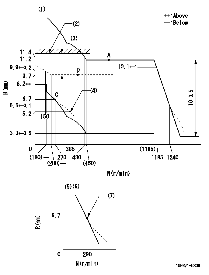
N:Pump speed
R:Rack position (mm)
(1)Tolerance for racks not indicated: +-0.05mm.
(2)Rack limit using stop lever
(3)Boost compensator stroke: BCL
(4)Damper spring setting
(5)Variable speed specification: idling adjustment
(6)Fix the lever at the full-load position at delivery.
(7)Main spring setting
----------
BCL=(2.2)mm
----------
----------
BCL=(2.2)mm
----------
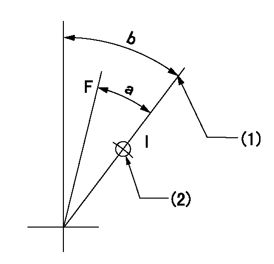
Speed control lever angle

F:Full speed
I:Idle
(1)Pump speed = aa
(2)Set the stopper bolt (fixed at full-load position at delivery.)
----------
aa=290r/min
----------
a=(16deg)+-5deg b=(7deg)+-5deg
----------
aa=290r/min
----------
a=(16deg)+-5deg b=(7deg)+-5deg
0000000901
F:Full load
I:Idle
(1)Stopper bolt setting
(2)Use the hole at R = aa
----------
aa=42mm
----------
a=29.5deg+-3deg b=45deg+-5deg
----------
aa=42mm
----------
a=29.5deg+-3deg b=45deg+-5deg
Stop lever angle
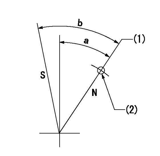
N:Pump normal
S:Stop the pump.
(1)Rack position = aa (at speed = bb)
(2)Use the pin above R = cc
----------
aa=11.8+0.2mm bb=350r/min cc=45mm
----------
a=(35deg)+-5deg b=38deg+-5deg
----------
aa=11.8+0.2mm bb=350r/min cc=45mm
----------
a=(35deg)+-5deg b=38deg+-5deg
0000001501 TAMPER PROOF
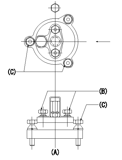
Tamperproofing-equipped boost compensator cover installation procedure
(A): figure shown by arrow
(B): after boost compensator adjustment, assemble and break off the screw head.
(C): specified torque
(1)Before adjusting the governor and the boost compensator, tighten the screw to the specified torque.
(Tightening torque T = T1 maximum)
(2)After adjusting the governor and the boost compensator, tighten to the specified torque to break off the bolt heads.
(Tightening torque T = T2)
----------
T1=2.5N-m(0.25kgf-m) T2=2.9~4.4N-m(0.3~0.45kgf-m)
----------
----------
T1=2.5N-m(0.25kgf-m) T2=2.9~4.4N-m(0.3~0.45kgf-m)
----------
Timing setting

(1)Pump vertical direction
(2)Coupling's key groove position at No 1 cylinder's beginning of injection
(3)-
(4)-
----------
----------
a=(25deg)
----------
----------
a=(25deg)
Information:
A measurement of fuel consumption is used to check fuel system performance. If fuel consumption of an engine is within the tolerance of specifications shown in the Fuel Setting And Related Information Fiche, the fuel system is performing correctly and no additional time should be spent checking fuel delivery.Fuel consumption - If the specified amount of fuel is being injected into the engine, the fuel delivery specification is being met. Therefore, the basic fuel system (fuel pump and lines, transfer pump, filters and primary fuel pressure) is within functional limits. Additional time spent troubleshooting these components is probably not justified.Fuel system timing - Fuel cannot be burned efficiently if it is not injected into the cylinder at the correct time. Because engines only develop horsepower when they are running, timing must be measured when they are running. The pin timing of the engine is not adequate. Timing must be measured throughout the speed range (this also checks the timing advance operation).Intake manifold pressure - Manifold pressure is an indication of the overall health of the engine. Boost is affected by any one or all of the following: fuel consumption, compression (valve condition, piston ring condition), turbocharger performance, intake restriction (air filters), exhaust restriction (muffler) or timing.Recommended Procedure With Chassis Dynamometer
Possible Causes/Corrections 1. Check Records Used To Determine Fuel ConsumptionMake sure the records are accurate. The minimum period for accurate fuel records is one month or 10,000 miles. Check the tires (air pressure and size), the gap between the tractor and trailer, air deflectors, trailer width, trailer type, engine cooling fan and driver habits. See "Owner/Operator Input" section for more information on the questions that should be asked. 2. Minor Operating FaultsTo help identify a problem before a more involved troubleshooting procedure is started, follow the procedure given in the "Primary Engine Checks" section. 3. Fuel Ratio Control Out Of Adjustment Or DefectiveFollow the procedure in the Testing and Adjusting section of this Service Manual. 4. Check Engine PerformanceDo a Power Analysis Report (PAR), Level II, to check engine performance. Refer to LEBV2810 and SEHS7886 for the tooling and procedures to use. Be sure to make a record of the temperatures for inlet air, fuel (at filter base), lubricating oil and coolant. Also, check for excessive exhaust smoke.At this point, the governor fuel settings should be verified. See the Testing and Adjusting Section of this Service Manual for the correct procedures to use. Also refer back to the information learned earlier (see "Owner Operator Input" section) about truck specifications and application and judge whether or not the engine is performing as expected or customer expectation is realistic. 5. Worn Fuel NozzlesCheck the horsepower on a dynamometer as in Step 4 above. Make a replacement of the fuel injection nozzles and check the horsepower output again. If there is more than 10 hp difference the old nozzles had eroded orifices and were causing high fuel rate.An alternate test is to lower the fuel setting to get the correct hp output.
Possible Causes/Corrections 1. Check Records Used To Determine Fuel ConsumptionMake sure the records are accurate. The minimum period for accurate fuel records is one month or 10,000 miles. Check the tires (air pressure and size), the gap between the tractor and trailer, air deflectors, trailer width, trailer type, engine cooling fan and driver habits. See "Owner/Operator Input" section for more information on the questions that should be asked. 2. Minor Operating FaultsTo help identify a problem before a more involved troubleshooting procedure is started, follow the procedure given in the "Primary Engine Checks" section. 3. Fuel Ratio Control Out Of Adjustment Or DefectiveFollow the procedure in the Testing and Adjusting section of this Service Manual. 4. Check Engine PerformanceDo a Power Analysis Report (PAR), Level II, to check engine performance. Refer to LEBV2810 and SEHS7886 for the tooling and procedures to use. Be sure to make a record of the temperatures for inlet air, fuel (at filter base), lubricating oil and coolant. Also, check for excessive exhaust smoke.At this point, the governor fuel settings should be verified. See the Testing and Adjusting Section of this Service Manual for the correct procedures to use. Also refer back to the information learned earlier (see "Owner Operator Input" section) about truck specifications and application and judge whether or not the engine is performing as expected or customer expectation is realistic. 5. Worn Fuel NozzlesCheck the horsepower on a dynamometer as in Step 4 above. Make a replacement of the fuel injection nozzles and check the horsepower output again. If there is more than 10 hp difference the old nozzles had eroded orifices and were causing high fuel rate.An alternate test is to lower the fuel setting to get the correct hp output.
Have questions with 106671-5800?
Group cross 106671-5800 ZEXEL
Nissan-Diesel
106671-5800
9 400 616 880
1671496504
INJECTION-PUMP ASSEMBLY
PE6T
PE6T