Information injection-pump assembly
BOSCH
9 400 616 874
9400616874
ZEXEL
106671-5730
1066715730
NISSAN-DIESEL
1671496501
1671496501
Rating:
Service parts 106671-5730 INJECTION-PUMP ASSEMBLY:
1.
_
7.
COUPLING PLATE
8.
_
9.
_
11.
Nozzle and Holder
16600-96520
12.
Open Pre:MPa(Kqf/cm2)
22.6{230}

15.
NOZZLE SET
Include in #1:
106671-5730
as INJECTION-PUMP ASSEMBLY
Cross reference number
BOSCH
9 400 616 874
9400616874
ZEXEL
106671-5730
1066715730
NISSAN-DIESEL
1671496501
1671496501
Zexel num
Bosch num
Firm num
Name
106671-5730
9 400 616 874
1671496501 NISSAN-DIESEL
INJECTION-PUMP ASSEMBLY
PE6TA K 14CA INJECTION PUMP ASSY PE6P,6PD PE
PE6TA K 14CA INJECTION PUMP ASSY PE6P,6PD PE
Calibration Data:
Adjustment conditions
Test oil
1404 Test oil ISO4113 or {SAEJ967d}
1404 Test oil ISO4113 or {SAEJ967d}
Test oil temperature
degC
40
40
45
Nozzle and nozzle holder
105780-8140
Bosch type code
EF8511/9A
Nozzle
105780-0000
Bosch type code
DN12SD12T
Nozzle holder
105780-2080
Bosch type code
EF8511/9
Opening pressure
MPa
17.2
Opening pressure
kgf/cm2
175
Injection pipe
Outer diameter - inner diameter - length (mm) mm 8-3-600
Outer diameter - inner diameter - length (mm) mm 8-3-600
Overflow valve
132424-0620
Overflow valve opening pressure
kPa
157
123
191
Overflow valve opening pressure
kgf/cm2
1.6
1.25
1.95
Tester oil delivery pressure
kPa
157
157
157
Tester oil delivery pressure
kgf/cm2
1.6
1.6
1.6
Direction of rotation (viewed from drive side)
Right R
Right R
Injection timing adjustment
Direction of rotation (viewed from drive side)
Right R
Right R
Injection order
1-4-2-6-
3-5
Pre-stroke
mm
3.65
3.6
3.7
Beginning of injection position
Drive side NO.1
Drive side NO.1
Difference between angles 1
Cal 1-4 deg. 60 59.5 60.5
Cal 1-4 deg. 60 59.5 60.5
Difference between angles 2
Cyl.1-2 deg. 120 119.5 120.5
Cyl.1-2 deg. 120 119.5 120.5
Difference between angles 3
Cal 1-6 deg. 180 179.5 180.5
Cal 1-6 deg. 180 179.5 180.5
Difference between angles 4
Cal 1-3 deg. 240 239.5 240.5
Cal 1-3 deg. 240 239.5 240.5
Difference between angles 5
Cal 1-5 deg. 300 299.5 300.5
Cal 1-5 deg. 300 299.5 300.5
Injection quantity adjustment
Adjusting point
A
Rack position
11.8
Pump speed
r/min
650
650
650
Average injection quantity
mm3/st.
166.5
164.5
168.5
Max. variation between cylinders
%
0
-4
4
Basic
*
Fixing the lever
*
Boost pressure
kPa
76
76
Boost pressure
mmHg
570
570
Hydraulic cylinder OFF
*
Injection quantity adjustment_02
Adjusting point
C
Rack position
6.7+-0.5
Pump speed
r/min
270
270
270
Average injection quantity
mm3/st.
15.5
14.5
16.5
Max. variation between cylinders
%
0
-10
10
Fixing the rack
*
Boost pressure
kPa
0
0
0
Boost pressure
mmHg
0
0
0
Hydraulic cylinder OFF
*
Injection quantity adjustment_03
Adjusting point
D
Rack position
9.75
Pump speed
r/min
400
400
400
Average injection quantity
mm3/st.
110
107
113
Fixing the lever
*
Boost pressure
kPa
0
0
0
Boost pressure
mmHg
0
0
0
Hydraulic cylinder OFF
*
Boost compensator adjustment
Pump speed
r/min
400
400
400
Rack position
9.75
Boost pressure
kPa
20
18.7
21.3
Boost pressure
mmHg
150
140
160
Boost compensator adjustment_02
Pump speed
r/min
400
400
400
Rack position
11.8
Boost pressure
kPa
46
42
50
Boost pressure
mmHg
345
315
375
Boost compensator adjustment_03
Pump speed
r/min
400
400
400
Rack position
(12.8)
Boost pressure
kPa
62.7
62.7
62.7
Boost pressure
mmHg
470
470
470
Timer adjustment
Pump speed
r/min
875--
Advance angle
deg.
0
0
0
Remarks
Start
Start
Timer adjustment_02
Pump speed
r/min
825
Advance angle
deg.
0.5
Timer adjustment_03
Pump speed
r/min
925
Advance angle
deg.
1
0.5
1.5
Remarks
Finish
Finish
Test data Ex:
Governor adjustment
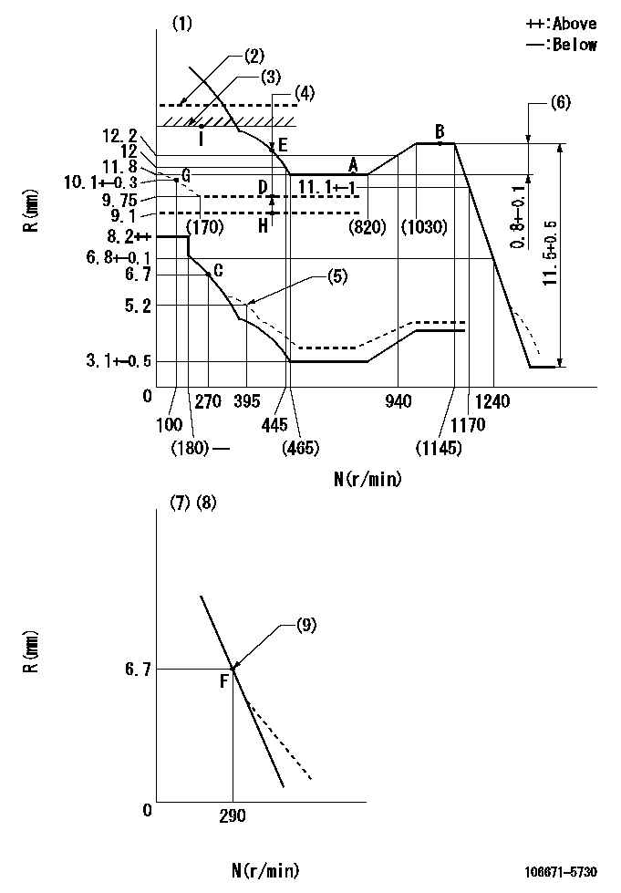
N:Pump speed
R:Rack position (mm)
(1)Tolerance for racks not indicated: +-0.05mm.
(2)Solenoid boost compensator OFF: SBL
(3)Rack limit using the stop lever: R1
(4)Boost compensator stroke: BCL
(5)Damper spring setting
(6)Rack difference between N = N1 and N = N2
(7)Variable speed specification: idling adjustment
(8)Fix the lever at the full-load position at delivery.
(9)Main spring setting
----------
SBL=(13.1)mm R1=12.8+0.2mm BCL=(3.05)mm N1=1100r/min N2=650r/min
----------
----------
SBL=(13.1)mm R1=12.8+0.2mm BCL=(3.05)mm N1=1100r/min N2=650r/min
----------
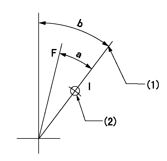
Speed control lever angle

F:Full speed
I:Idle
(1)Pump speed = aa
(2)Set the stopper bolt (fixed at full-load position at delivery.)
----------
aa=290r/min
----------
a=(16deg)+-5deg b=(8deg)+-5deg
----------
aa=290r/min
----------
a=(16deg)+-5deg b=(8deg)+-5deg
0000000901
F:Full load
I:Idle
(1)Stopper bolt setting
(2)Use the hole at R = aa
----------
aa=42mm
----------
a=31.5deg+-3deg b=45deg+-5deg
----------
aa=42mm
----------
a=31.5deg+-3deg b=45deg+-5deg
Stop lever angle
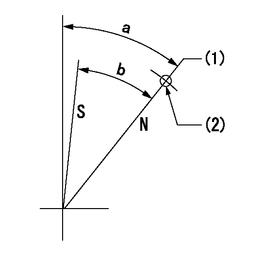
N:Pump normal
S:Stop the pump.
(1)Rack position aa (pump speed bb r/min )
(2)Use the pin above R = cc
----------
aa=12.8+0.2mm bb=350r/min cc=40mm
----------
a=(42deg)+-5deg b=41deg+-5deg
----------
aa=12.8+0.2mm bb=350r/min cc=40mm
----------
a=(42deg)+-5deg b=41deg+-5deg
0000001501 BCS

(A) Screw for precise adjustment
(B) Pre-adjustment screw
(C) Control rack, rack decrease direction
(D) Rack limit
1. Solenoid boost compensator adjustment
(1)Supply DC: V1 to the solenoid terminals and confirm solenoid operation.
(2)With the solenoid ON, calculate L1 from the value of R1. [L1 = La - (10.5 - R1) +-0.2]
(3)Adjust (B) to obtain L1.
(4)Assemble the solenoid to the governor.
(5)With the solenoid ON, readjust (B) so that R1 is within the allowance a.
(6)With the solenoid OFF, perform all governor adjustments except rack limit adjustment.
(7)Set the pump speed at N1 and turn the solenoid ON.
(8)Adjust (A) so that R1 is within the allowance range a.
(9)Set the pump speed at N1 and fix the load lever in the full position
(10)Turn the solenoid switch ON and OFF several times and confirm that the difference in rack positions is within L2.
(11)Set the rack limit.
(12)Stamp the solenoid valve.
----------
V1=24V N1=400r/min N2=0r/min R1=9.1mm a=+-0.5mm La=28mm L1=26.6+-0.2mm L2=3.5~5mm
----------
----------
V1=24V N1=400r/min N2=0r/min R1=9.1mm a=+-0.5mm La=28mm L1=26.6+-0.2mm L2=3.5~5mm
----------
Timing setting

(1)Pump vertical direction
(2)Coupling's key groove position at No 1 cylinder's beginning of injection
(3)-
(4)-
----------
----------
a=(30deg)
----------
----------
a=(30deg)
Information:
Start By:a. remove engine balancer group (3114 Engines)b. remove oil pump (3116 Engines) 1. Remove bolts (1), the washers and bearing cap (2). Remove the lower main bearing half from the cap.
If the crankshaft is turned in the wrong direction during upper main bearing half removal, the tab of the bearing will be pushed between the crankshaft and the cylinder block. This can cause result in damage to either or both the crankshaft and the cylinder block.
Both the center and two end main journals have no oil hole. To remove these upper main bearing halves, put a thin piece of soft material, (that will not damage the crankshaft journal), against the end of the bearing half, opposite the tab. Hit the bearing with the soft material until the tab of the bearing is free from the groove in the cylinder block.2. Remove the upper half of the main bearings as follows: a. Turn the crankshaft until Tool (A) can be installed in the crankshaft journal. Install Tool (A) as shown.b. Turn the crankshaft in the direction which will push the upper main bearing half out, tab end first.c. Check the condition of the main bearings. Refer to "Guideline For Reusable Parts, Main & Connecting Rod Bearings", Form No. SEBF8009 and SEBD0531 as guide for checking bearing condition. The following steps are for the installation of the crankshaft main bearings.3. Clean the bearing surfaces in the cylinder block for the main bearings. Apply clean engine oil on the upper main bearing half. Do not put oil on the back side of the bearing. Using Tool (A), install the upper main bearing half (bearings with the oil holes) in the cylinder block. Be sure the tab on the back side of the bearing engages with the groove in the cylinder block.4. Clean the bearing surface of the main bearing caps. Install the lower main bearing half in the main bearing cap. Be sure the tab on the back side of the bearing engages with the groove in the main bearing cap. Apply clean engine oil on the lower main bearing half. Do no put oil on the back side of the bearing.5. Install the main bearing caps as follows:
Install the main bearing caps with the sequence number to the right, 1 through 5 (for the 4 cylinder) and 1 through 7 (for the 6 cylinder), front to rear.
a. Put main bearing caps (2) in position in the cylinder block with the sequence numbers in the correct positions.b. Apply clean engine oil to the threads of the main bearing cap mounting bolts and on the washer contact faces.c. Install main bearing cap mounting bolts (1) and the washers. Tighten both bolts of each main bearing cap to a torque of 54 7 N m (40 5 lb ft).d. Tighten the bolts and additional 1/4 90 5 degrees ( turn). 6. Check the end play of the crankshaft with Tool (B). The end play of the crankshaft
Have questions with 106671-5730?
Group cross 106671-5730 ZEXEL
Nissan-Diesel
106671-5730
9 400 616 874
1671496501
INJECTION-PUMP ASSEMBLY
PE6TA
PE6TA