Information injection-pump assembly
BOSCH
9 400 616 871
9400616871
ZEXEL
106671-5690
1066715690
NISSAN-DIESEL
1679096608
1679096608
Rating:
Service parts 106671-5690 INJECTION-PUMP ASSEMBLY:
1.
_
7.
COUPLING PLATE
8.
_
9.
_
11.
Nozzle and Holder
1660096611
12.
Open Pre:MPa(Kqf/cm2)
18.6{190}/22.6{230}
14.
NOZZLE
Include in #1:
106671-5690
as INJECTION-PUMP ASSEMBLY
Cross reference number
BOSCH
9 400 616 871
9400616871
ZEXEL
106671-5690
1066715690
NISSAN-DIESEL
1679096608
1679096608
Zexel num
Bosch num
Firm num
Name
106671-5690
9 400 616 871
1679096608 NISSAN-DIESEL
INJECTION-PUMP ASSEMBLY
PF6T24 K 14CA INJECTION PUMP ASSY PE6P,6PD PE
PF6T24 K 14CA INJECTION PUMP ASSY PE6P,6PD PE
Calibration Data:
Adjustment conditions
Test oil
1404 Test oil ISO4113 or {SAEJ967d}
1404 Test oil ISO4113 or {SAEJ967d}
Test oil temperature
degC
40
40
45
Nozzle and nozzle holder
105780-8140
Bosch type code
EF8511/9A
Nozzle
105780-0000
Bosch type code
DN12SD12T
Nozzle holder
105780-2080
Bosch type code
EF8511/9
Opening pressure
MPa
17.2
Opening pressure
kgf/cm2
175
Injection pipe
Outer diameter - inner diameter - length (mm) mm 8-3-600
Outer diameter - inner diameter - length (mm) mm 8-3-600
Overflow valve
134424-0020
Overflow valve opening pressure
kPa
157
123
191
Overflow valve opening pressure
kgf/cm2
1.6
1.25
1.95
Tester oil delivery pressure
kPa
157
157
157
Tester oil delivery pressure
kgf/cm2
1.6
1.6
1.6
Direction of rotation (viewed from drive side)
Right R
Right R
Injection timing adjustment
Direction of rotation (viewed from drive side)
Right R
Right R
Injection order
1-4-2-6-
3-5
Pre-stroke
mm
3.9
3.85
3.95
Beginning of injection position
Drive side NO.1
Drive side NO.1
Difference between angles 1
Cal 1-4 deg. 60 59.5 60.5
Cal 1-4 deg. 60 59.5 60.5
Difference between angles 2
Cyl.1-2 deg. 120 119.5 120.5
Cyl.1-2 deg. 120 119.5 120.5
Difference between angles 3
Cal 1-6 deg. 180 179.5 180.5
Cal 1-6 deg. 180 179.5 180.5
Difference between angles 4
Cal 1-3 deg. 240 239.5 240.5
Cal 1-3 deg. 240 239.5 240.5
Difference between angles 5
Cal 1-5 deg. 300 299.5 300.5
Cal 1-5 deg. 300 299.5 300.5
Injection quantity adjustment
Adjusting point
A
Rack position
12
Pump speed
r/min
1050
1050
1050
Average injection quantity
mm3/st.
175.5
173.5
177.5
Max. variation between cylinders
%
0
-4
4
Basic
*
Fixing the lever
*
Boost pressure
kPa
72
72
Boost pressure
mmHg
540
540
Injection quantity adjustment_02
Adjusting point
C
Rack position
6.5+-0.5
Pump speed
r/min
300
300
300
Average injection quantity
mm3/st.
14.5
13.5
15.5
Max. variation between cylinders
%
0
-10
10
Fixing the rack
*
Boost pressure
kPa
0
0
0
Boost pressure
mmHg
0
0
0
Boost compensator adjustment
Pump speed
r/min
300
300
300
Rack position
9.6
Boost pressure
kPa
6.7
1.4
12
Boost pressure
mmHg
50
10
90
Boost compensator adjustment_02
Pump speed
r/min
300
300
300
Rack position
12
Boost pressure
kPa
37.3
34.6
40
Boost pressure
mmHg
280
260
300
Boost compensator adjustment_03
Pump speed
r/min
300
300
300
Rack position
(13.2)
Boost pressure
kPa
58.7
58.7
58.7
Boost pressure
mmHg
440
440
440
Timer adjustment
Pump speed
r/min
750--
Advance angle
deg.
0
0
0
Remarks
Start
Start
Timer adjustment_02
Pump speed
r/min
700
Advance angle
deg.
0.5
Timer adjustment_03
Pump speed
r/min
1050
Advance angle
deg.
2
1.5
2.5
Remarks
Finish
Finish
Test data Ex:
Governor adjustment
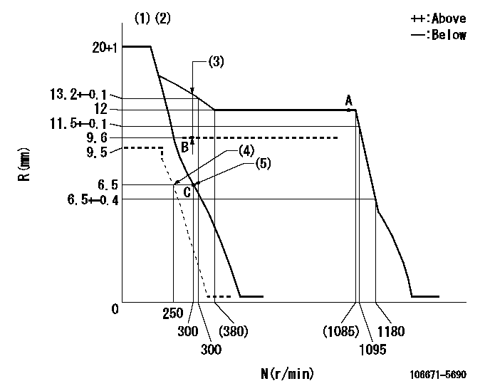
N:Pump speed
R:Rack position (mm)
(1)Target notch: K
(2)Tolerance for racks not indicated: +-0.05mm.
(3)Boost compensator stroke: BCL
(4)Set idle sub-spring
(5)Main spring setting
----------
K=9 BCL=(3.6)mm
----------
----------
K=9 BCL=(3.6)mm
----------
Speed control lever angle

F:Full speed
I:Idle
(1)Stopper bolt setting
----------
----------
a=(10deg)+-5deg b=(22deg)+-5deg
----------
----------
a=(10deg)+-5deg b=(22deg)+-5deg
Stop lever angle

N:Pump normal
S:Stop the pump.
----------
----------
a=26.5deg+-5deg b=53deg+-5deg
----------
----------
a=26.5deg+-5deg b=53deg+-5deg
0000001501 GOV FULL LOAD ADJUSTMENT

Title1:Full load stopper adjustment
Title2:Governor set speed
LABEL1:Distinguishing
LABEL2:Pump speed (r/min)
LABEL3:Ave. injection quantity (mm3/st)
LABEL4:Max. var. bet. cyl.
LABEL5:Remarks
LABEL6:Distinguishing
LABEL7:Governor set speed (r/min)
LABEL8:Maximum no-load speed (r/min)
LABEL9:Remarks
(1)Adjustment conditions are the same as those for measuring injection quantity.
(2)At high idle rack position L
----------
L=6.5mm
----------
a1=B a2=- a3=- a4=- r1=1050r/min r2=- r3=- r4=- Q1=175.5+-2mm3/st Q2=- Q3=- Q4=- c1=+-4% c2=- c3=- c4=- a5=21 a6=20 a7=19 a8=18 a9=17 a10=16 a11=15 a12=14 a13=- a14=- a15=- r5=1050r/min r6=1000r/min r7=950r/min r8=900r/min r9=850r/min r10=800r/min r11=750r/min r12=700r/min r13=- r14=- r15=- R5=1130+-26r/min R6=1075+-25r/min R7=1020+-23r/min R8=965+-22r/min R9=915+-22r/min R10=865+-20r/min R11=820+-18r/min R12=775+-18r/min R13=- R14=- R15=-
----------
L=6.5mm
----------
a1=B a2=- a3=- a4=- r1=1050r/min r2=- r3=- r4=- Q1=175.5+-2mm3/st Q2=- Q3=- Q4=- c1=+-4% c2=- c3=- c4=- a5=21 a6=20 a7=19 a8=18 a9=17 a10=16 a11=15 a12=14 a13=- a14=- a15=- r5=1050r/min r6=1000r/min r7=950r/min r8=900r/min r9=850r/min r10=800r/min r11=750r/min r12=700r/min r13=- r14=- r15=- R5=1130+-26r/min R6=1075+-25r/min R7=1020+-23r/min R8=965+-22r/min R9=915+-22r/min R10=865+-20r/min R11=820+-18r/min R12=775+-18r/min R13=- R14=- R15=-
Timing setting

(1)Pump vertical direction
(2)Coupling's key groove position at No 1 cylinder's beginning of injection
(3)-
(4)-
----------
----------
a=(20deg)
----------
----------
a=(20deg)
Information:
1. Remove the bolts that hold the cylinder head assembly to the cylinder block.
To prevent damage to the two cylinder head-to-cylinder block dowels, keep the cylinder head assembly level during removal and installation.
2. Fasten a hoist to the cylinder head assembly as shown. Carefully remove the cylinder head assembly from the cylinder block. Remove the cylinder head gasket. The weight of the cylinder head assembly can range from 50 to 75 kg (110 to 165 lb). The following steps are for the installation of the cylinder head assembly.3. Be sure the mating surface of the cylinder head assembly and the cylinder block are thoroughly clean.4. Put a new cylinder head gasket in position on the cylinder block. Be sure the head gasket is dry. Fasten a hoist to the cylinder head assembly, and put it in position on the cylinder block.
3114 Cylinder Head Tightening Sequence
3116 Cylinder Head Tightening Sequence Bolts (1) are large diameter bolts (M20). Bolts (2) are small diameter bolts (M10).5. Apply clean engine oil on the threads of the cylinder head assembly mounting bolts.6. Install the bolts that hold the cylinder head assembly to the cylinder block, and tighten them as follows: a. Tighten the large diameter bolts in the number sequence shown to a torque of 150 15 N m (110 11 lb ft).b. Tighten the large diameter bolts in the number sequence shown to a torque of 435 20 N m (320 15 lb ft).c. Retorque the large diameter bolts in the number sequence shown to a torque of 435 20 N m (320 15 lb ft).d. Tighten the small diameter bolts in the number sequence shown to a torque of 55 7 N m (41 5 lb ft).End By:a. install unit fuel injectorsb. install fuel control linkagec. install rocker arm assemblies and push rodsd. install inlet manifolde. install exhaust manifoldf. install fuel filter and fuel filter base
Have questions with 106671-5690?
Group cross 106671-5690 ZEXEL
Nissan-Diesel
Nissan-Diesel
Nissan-Diesel
Nissan-Diesel
106671-5690
9 400 616 871
1679096608
INJECTION-PUMP ASSEMBLY
PF6T24
PF6T24