Information injection-pump assembly
BOSCH
9 400 616 870
9400616870
ZEXEL
106671-5681
1066715681
NISSAN-DIESEL
1679096607
1679096607
Rating:
Service parts 106671-5681 INJECTION-PUMP ASSEMBLY:
1.
_
7.
COUPLING PLATE
8.
_
9.
_
11.
Nozzle and Holder
16600-96609
12.
Open Pre:MPa(Kqf/cm2)
17.7{180}/22.6{230}
15.
NOZZLE SET
Include in #1:
106671-5681
as INJECTION-PUMP ASSEMBLY
Cross reference number
BOSCH
9 400 616 870
9400616870
ZEXEL
106671-5681
1066715681
NISSAN-DIESEL
1679096607
1679096607
Zexel num
Bosch num
Firm num
Name
106671-5681
9 400 616 870
1679096607 NISSAN-DIESEL
INJECTION-PUMP ASSEMBLY
PF6TA K 14CA INJECTION PUMP ASSY PE6P,6PD PE
PF6TA K 14CA INJECTION PUMP ASSY PE6P,6PD PE
Calibration Data:
Adjustment conditions
Test oil
1404 Test oil ISO4113 or {SAEJ967d}
1404 Test oil ISO4113 or {SAEJ967d}
Test oil temperature
degC
40
40
45
Nozzle and nozzle holder
105780-8140
Bosch type code
EF8511/9A
Nozzle
105780-0000
Bosch type code
DN12SD12T
Nozzle holder
105780-2080
Bosch type code
EF8511/9
Opening pressure
MPa
17.2
Opening pressure
kgf/cm2
175
Injection pipe
Outer diameter - inner diameter - length (mm) mm 8-3-600
Outer diameter - inner diameter - length (mm) mm 8-3-600
Overflow valve
134424-0020
Overflow valve opening pressure
kPa
157
123
191
Overflow valve opening pressure
kgf/cm2
1.6
1.25
1.95
Tester oil delivery pressure
kPa
157
157
157
Tester oil delivery pressure
kgf/cm2
1.6
1.6
1.6
Direction of rotation (viewed from drive side)
Right R
Right R
Injection timing adjustment
Direction of rotation (viewed from drive side)
Right R
Right R
Injection order
1-4-2-6-
3-5
Pre-stroke
mm
3.9
3.85
3.95
Beginning of injection position
Drive side NO.1
Drive side NO.1
Difference between angles 1
Cal 1-4 deg. 60 59.5 60.5
Cal 1-4 deg. 60 59.5 60.5
Difference between angles 2
Cyl.1-2 deg. 120 119.5 120.5
Cyl.1-2 deg. 120 119.5 120.5
Difference between angles 3
Cal 1-6 deg. 180 179.5 180.5
Cal 1-6 deg. 180 179.5 180.5
Difference between angles 4
Cal 1-3 deg. 240 239.5 240.5
Cal 1-3 deg. 240 239.5 240.5
Difference between angles 5
Cal 1-5 deg. 300 299.5 300.5
Cal 1-5 deg. 300 299.5 300.5
Injection quantity adjustment
Adjusting point
A
Rack position
11.4
Pump speed
r/min
700
700
700
Average injection quantity
mm3/st.
181.5
179.5
183.5
Max. variation between cylinders
%
0
-4
4
Basic
*
Fixing the lever
*
Boost pressure
kPa
89.3
89.3
Boost pressure
mmHg
670
670
Injection quantity adjustment_02
Adjusting point
D
Rack position
6.4+-0.5
Pump speed
r/min
375
375
375
Average injection quantity
mm3/st.
18.5
17.5
19.5
Max. variation between cylinders
%
0
-10
10
Fixing the rack
*
Boost pressure
kPa
0
0
0
Boost pressure
mmHg
0
0
0
Boost compensator adjustment
Pump speed
r/min
500
500
500
Rack position
9.4
Boost pressure
kPa
8
2.7
13.3
Boost pressure
mmHg
60
20
100
Boost compensator adjustment_02
Pump speed
r/min
500
500
500
Rack position
(11.4)
Boost pressure
kPa
80
77.3
82.7
Boost pressure
mmHg
600
580
620
Timer adjustment
Pump speed
r/min
750--
Advance angle
deg.
0
0
0
Remarks
Start
Start
Timer adjustment_02
Pump speed
r/min
700
Advance angle
deg.
0.5
Timer adjustment_03
Pump speed
r/min
1050
Advance angle
deg.
2
1.5
2.5
Remarks
Finish
Finish
Test data Ex:
Governor adjustment
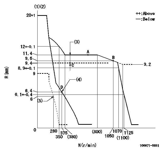
N:Pump speed
R:Rack position (mm)
(1)Target notch: K
(2)Tolerance for racks not indicated: +-0.05mm.
(3)Boost compensator stroke: BCL
(4)Main spring setting
(5)Set idle sub-spring
----------
K=18 BCL=(2)mm
----------
----------
K=18 BCL=(2)mm
----------
Speed control lever angle

F:Full speed
I:Idle
(1)Stopper bolt setting
----------
----------
a=12deg+-5deg b=20deg+-5deg
----------
----------
a=12deg+-5deg b=20deg+-5deg
Stop lever angle

N:Pump normal
S:Stop the pump.
----------
----------
a=26deg+-5deg b=53deg+-5deg
----------
----------
a=26deg+-5deg b=53deg+-5deg
0000001501 GOV FULL LOAD ADJUSTMENT
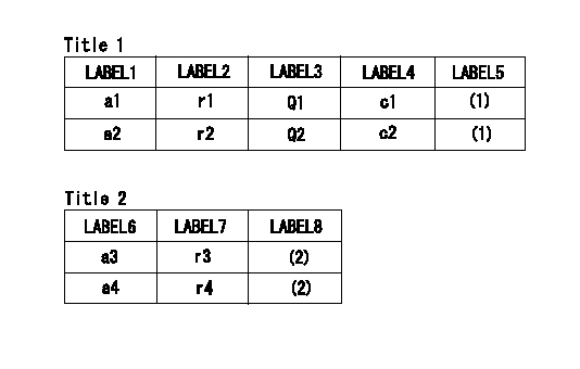
Title1:Full load stopper adjustment
Title2:Governor set speed
LABEL1:Distinguishing
LABEL2:Pump speed (r/min)
LABEL3:Ave. injection quantity (mm3/st)
LABEL4:Max. var. bet. cyl.
LABEL5:Remarks
LABEL6:Distinguishing
LABEL7:Governor set speed (r/min)
LABEL8:Remarks
(1)Adjustment conditions are the same as those for measuring injection quantity.
(2)-
----------
----------
a1=B a2=- r1=700r/min r2=- Q1=181.5+-2mm3/st Q2=- c1=+-4% c2=- a3=21 a4=20 r3=1050r/min r4=1000r/min
----------
----------
a1=B a2=- r1=700r/min r2=- Q1=181.5+-2mm3/st Q2=- c1=+-4% c2=- a3=21 a4=20 r3=1050r/min r4=1000r/min
Timing setting

(1)Pump vertical direction
(2)Coupling's key groove position at No 1 cylinder's beginning of injection
(3)-
(4)-
----------
----------
a=(25deg)
----------
----------
a=(25deg)
Information:
Start By:a. remove rocker arm assemblies and push rods1. Disconnect the governor control linkage. See the 3114 & 3116 Engines Governor Service Manual, Form No. SENR6454.
Do not move the fuel control linkage or the injector racks with out the Injector Compressors [Tool (A)] installed. Damage to the fuel injectors can result. After installation of Tool (A), tap on the top of each fuel injector lightly with a rubber mallet to prevent any binding or side loading in the fuel injectors.
2. When removing the fuel control linkage with the fuel injectors in place, install Tool (A) on the fuel injectors, and slightly compress the injector springs.3. Remove four bolts (1) and fuel control linkage (2). The following steps are for the installation of the fuel control linkage.4. Be sure the two screws in each inboard bracket are loose.5. Put fuel control linkage in position on the cylinder head assembly. Be sure all injector racks are engaged and the small dowel in each mounting bracket is in the proper position before tightening bolts (1). Install four bolts (1), and tighten them as follows: a. Tighten the two outer bearing bracket mounting bolts.b. Tighten the inner bearing bracket(s) mounting bolt(s).c. Position the inner bearing(s) to allow free rotation of the rack control rod.d. Tighten the two screws in on each inner bracket(s) to a torque of 3.5 0.2 N m (31 2 lb in).e. The control rod must rotate when a force of 4.4 N (1 lb) or less is applied to control lever (3) in the direction indicated by arrows.6. Connect the governor control linkage. See the 3114 & 3116 Engines Governor Service Manual, Form No. SENR6454.7. After installation of the rocker arm assemblies and push rods, Check and/or adjust the following: Injector Synchronization, Fuel Setting, Fuel Timing, Valve Lash. See the 3114 & 3116 Diesel Truck Engines Systems Operation Testing & Adjusting module, Form No. SENR6437 to check and/or adjust the above items.End By:a. install rocker arm assemblies and push rods
Have questions with 106671-5681?
Group cross 106671-5681 ZEXEL
Nissan-Diesel
Nissan-Diesel
Nissan-Diesel
Nissan-Diesel
106671-5681
9 400 616 870
1679096607
INJECTION-PUMP ASSEMBLY
PF6TA
PF6TA