Information injection-pump assembly
BOSCH
9 400 619 862
9400619862
ZEXEL
106671-5670
1066715670
NISSAN-DIESEL
1680095505
1680095505
Rating:
Service parts 106671-5670 INJECTION-PUMP ASSEMBLY:
1.
_
7.
COUPLING PLATE
8.
_
9.
_
11.
Nozzle and Holder
12.
Open Pre:MPa(Kqf/cm2)
18.6(190)/22.6(230)
14.
NOZZLE
Include in #1:
106671-5670
as INJECTION-PUMP ASSEMBLY
Cross reference number
BOSCH
9 400 619 862
9400619862
ZEXEL
106671-5670
1066715670
NISSAN-DIESEL
1680095505
1680095505
Zexel num
Bosch num
Firm num
Name
9 400 619 862
1680095505 NISSAN-DIESEL
INJECTION-PUMP ASSEMBLY
NF6TA * K 14CA PE6P,6PD PE
NF6TA * K 14CA PE6P,6PD PE
Calibration Data:
Adjustment conditions
Test oil
1404 Test oil ISO4113 or {SAEJ967d}
1404 Test oil ISO4113 or {SAEJ967d}
Test oil temperature
degC
40
40
45
Nozzle and nozzle holder
105780-8140
Bosch type code
EF8511/9A
Nozzle
105780-0000
Bosch type code
DN12SD12T
Nozzle holder
105780-2080
Bosch type code
EF8511/9
Opening pressure
MPa
17.2
Opening pressure
kgf/cm2
175
Injection pipe
Outer diameter - inner diameter - length (mm) mm 8-3-600
Outer diameter - inner diameter - length (mm) mm 8-3-600
Overflow valve
134424-4120
Overflow valve opening pressure
kPa
255
221
289
Overflow valve opening pressure
kgf/cm2
2.6
2.25
2.95
Tester oil delivery pressure
kPa
157
157
157
Tester oil delivery pressure
kgf/cm2
1.6
1.6
1.6
Direction of rotation (viewed from drive side)
Right R
Right R
Injection timing adjustment
Direction of rotation (viewed from drive side)
Right R
Right R
Injection order
1-4-2-6-
3-5
Pre-stroke
mm
4.4
4.37
4.43
Beginning of injection position
Drive side NO.1
Drive side NO.1
Difference between angles 1
Cal 1-4 deg. 60 59.75 60.25
Cal 1-4 deg. 60 59.75 60.25
Difference between angles 2
Cyl.1-2 deg. 120 119.75 120.25
Cyl.1-2 deg. 120 119.75 120.25
Difference between angles 3
Cal 1-6 deg. 180 179.75 180.25
Cal 1-6 deg. 180 179.75 180.25
Difference between angles 4
Cal 1-3 deg. 240 239.75 240.25
Cal 1-3 deg. 240 239.75 240.25
Difference between angles 5
Cal 1-5 deg. 300 299.75 300.25
Cal 1-5 deg. 300 299.75 300.25
Injection quantity adjustment
Adjusting point
-
Rack position
13
Pump speed
r/min
650
650
650
Average injection quantity
mm3/st.
156.5
153.5
159.5
Max. variation between cylinders
%
0
-4
4
Basic
*
Fixing the rack
*
Standard for adjustment of the maximum variation between cylinders
*
Injection quantity adjustment_02
Adjusting point
Z
Rack position
8+-0.5
Pump speed
r/min
530
530
530
Average injection quantity
mm3/st.
10
9
11
Max. variation between cylinders
%
0
-10
10
Fixing the rack
*
Standard for adjustment of the maximum variation between cylinders
*
Injection quantity adjustment_03
Adjusting point
A
Rack position
R1(13)
Pump speed
r/min
650
650
650
Average injection quantity
mm3/st.
156.5
154.5
158.5
Basic
*
Fixing the lever
*
Boost pressure
kPa
46.7
46.7
Boost pressure
mmHg
350
350
Injection quantity adjustment_04
Adjusting point
B
Rack position
(R1+0.2)
Pump speed
r/min
1250
1250
1250
Average injection quantity
mm3/st.
127.5
121.5
133.5
Fixing the lever
*
Boost pressure
kPa
46.7
46.7
Boost pressure
mmHg
350
350
Injection quantity adjustment_05
Adjusting point
C
Rack position
R2(R1-1)
Pump speed
r/min
300
300
300
Average injection quantity
mm3/st.
149.5
143.5
155.5
Fixing the lever
*
Boost pressure
kPa
46.7
46.7
Boost pressure
mmHg
350
350
Injection quantity adjustment_06
Adjusting point
D
Rack position
R2-1.35
Pump speed
r/min
300
300
300
Average injection quantity
mm3/st.
81.5
75.5
87.5
Fixing the lever
*
Boost pressure
kPa
0
0
0
Boost pressure
mmHg
0
0
0
Boost compensator adjustment
Pump speed
r/min
300
300
300
Rack position
R2-1.35
Boost pressure
kPa
10.7
9.4
12
Boost pressure
mmHg
80
70
90
Boost compensator adjustment_02
Pump speed
r/min
300
300
300
Rack position
R2(R1-1)
Boost pressure
kPa
33.3
33.3
33.3
Boost pressure
mmHg
250
250
250
Test data Ex:
Governor adjustment
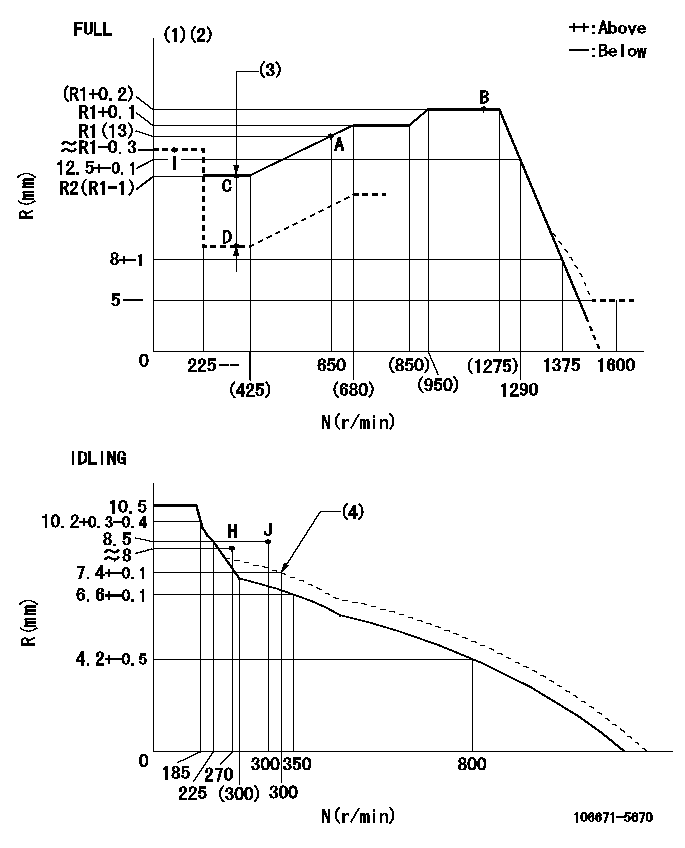
N:Pump speed
R:Rack position (mm)
(1)Torque cam stamping: T1
(2)Tolerance for racks not indicated: +-0.05mm.
(3)Boost compensator stroke: BCL
(4)Damper spring setting
----------
T1=AF12 BCL=1.35+-0.1mm
----------
----------
T1=AF12 BCL=1.35+-0.1mm
----------
Timer adjustment

(1)Adjusting range
(2)Step response time
(N): Speed of the pump
(L): Load
(theta) Advance angle
(Srd1) Step response time 1
(Srd2) Step response time 2
1. Adjusting conditions for the variable timer
(1)Adjust the clearance between the pickup and the protrusion to L.
----------
L=1-0.2mm N4=800r/min C4=(8deg) t1=2--sec. t2=2--sec.
----------
N1=400r/min N2=1000++r/min N3=1250r/min C1=8+-0.3deg C2=4++deg C3=4--deg P1=0kPa(0kgf/cm2) P2=196kPa(2kgf/cm2) P3=392kPa(4kgf/cm2) R01=0/4load R02=4/4load R03=4/4load
----------
L=1-0.2mm N4=800r/min C4=(8deg) t1=2--sec. t2=2--sec.
----------
N1=400r/min N2=1000++r/min N3=1250r/min C1=8+-0.3deg C2=4++deg C3=4--deg P1=0kPa(0kgf/cm2) P2=196kPa(2kgf/cm2) P3=392kPa(4kgf/cm2) R01=0/4load R02=4/4load R03=4/4load
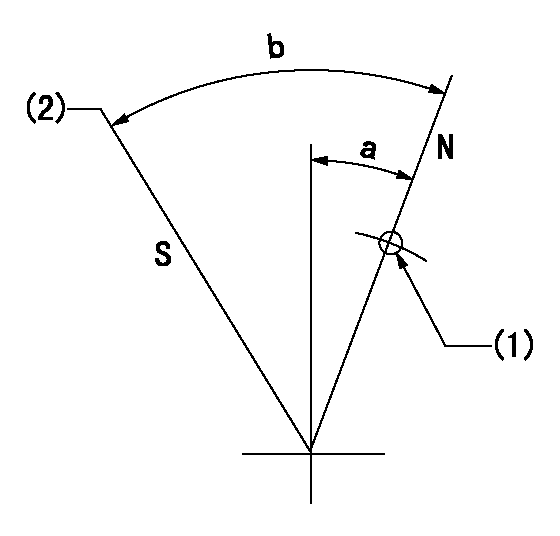
Speed control lever angle

F:Full speed
I:Idle
(1)Use the hole at R = aa
(2)Stopper bolt set position 'H'
----------
aa=34mm
----------
a=26deg+-5deg b=41deg+-3deg
----------
aa=34mm
----------
a=26deg+-5deg b=41deg+-3deg
Stop lever angle
N:Pump normal
S:Stop the pump.
(1)Use the pin at R = aa
(2)Set the stopper screw so that speed = bb and the rack position = cc (after setting apply red paint).
----------
aa=40mm bb=0r/min cc=1.5+-0.3mm
----------
a=20deg+-5deg b=44deg+-5deg
----------
aa=40mm bb=0r/min cc=1.5+-0.3mm
----------
a=20deg+-5deg b=44deg+-5deg
0000001501 RACK SENSOR

(VR) measurement voltage
(I) Part number of the control unit
(G) Apply red paint.
(H): End surface of the pump
1. Rack sensor adjustment (-0620)
(1)Fix the speed control lever at the full position
(2)Set the speed to N1 r/min.
(If the boost compensator is provided, apply boost pressure.)
(3)Adjust the bobbin (A) so that the rack sensor's output voltage is VR+-0.01.
(4)At that time, rack position must be Ra.
(5)Apply G at two places.
Connecting part between the joint (B) and the nut (F)
Connecting part between the joint (B) and the end surface of the pump (H)
----------
N1=650r/min Ra=R1(13)mm
----------
----------
N1=650r/min Ra=R1(13)mm
----------
Timing setting

(1)Pump vertical direction
(2)Coupling's key groove position at No 1 cylinder's beginning of injection
(3)-
(4)-
----------
----------
a=(25deg)
----------
----------
a=(25deg)
Information:
Start By:a. remove valve cover 1. Remove four bolts (1) that hold each rocker arm assembly in position. Remove the rocker arm assemblies from the engine.2. Put identification marks on all push rods as to their location in the engine. Remove the push rods from the engine. 3. Disassemble the rocker arm assemblies as follows: a. Remove the pin and rocker arm mounts (2). Remove the two rocker arm assemblies and the unit injector arm assembly from the shaft assembly.b. Remove the nut and valve adjusting screw (3) from each rocker arm.c. Remove arm button (7), retaining ring (6) and the arm socket from the unit injector arm.d. Loosen the nut, and remove injection adjusting screw (4) from the unit injector arm.e. Remove sleeve bearing (5) from the unit injector arm. The following steps are for the installation of the rocker arm assemblies and push rods.4. Be sure all parts of the rocker arm assemblies are clean.5. Assemble the rocker arm assemblies as follows: a. Install sleeve bearing (5) in the unit injector arm with Tool (A).b. Install injection adjusting screw (4) and the nut in the unit injector arm.c. Install the arm socket, retaining ring (6) and arm button (7) in the unit injector arm.d. Install valve adjusting screw (3) and the nut in each rocker arm.e. Put the rocker arm assemblies and the unit injector arm assembly in position on the shaft assembly. Install two rocker arm mounts (2) and the pins that hold them.6. Apply clean engine oil to the push rods, and install them in their original locations in the engine. Be sure the push rods are seated in the lifter arm assemblies.7. Loosen all adjusting screws in the rocker arm assemblies. Position the rocker arm assemblies on the cylinder head assembly, and install bolts (1) that hold them in position.8. Adjust the fuel timing and the valve lash. See the topics "Fuel Timing" & "Valve Lash" in the 3114 & 3116 Diesel truck Engines Systems Operation & Testing & Adjusting module, Form No. SENR6437.End By:a. install valve cover