Information injection-pump assembly
BOSCH
9 400 616 866
9400616866
ZEXEL
106671-5611
1066715611
NISSAN-DIESEL
1671396973
1671396973
Rating:
Service parts 106671-5611 INJECTION-PUMP ASSEMBLY:
1.
_
7.
COUPLING PLATE
8.
_
9.
_
11.
Nozzle and Holder
12.
Open Pre:MPa(Kqf/cm2)
22.6/230

15.
NOZZLE SET
Include in #1:
106671-5611
as INJECTION-PUMP ASSEMBLY
Cross reference number
BOSCH
9 400 616 866
9400616866
ZEXEL
106671-5611
1066715611
NISSAN-DIESEL
1671396973
1671396973
Zexel num
Bosch num
Firm num
Name
Calibration Data:
Adjustment conditions
Test oil
1404 Test oil ISO4113 or {SAEJ967d}
1404 Test oil ISO4113 or {SAEJ967d}
Test oil temperature
degC
40
40
45
Nozzle and nozzle holder
105780-8140
Bosch type code
EF8511/9A
Nozzle
105780-0000
Bosch type code
DN12SD12T
Nozzle holder
105780-2080
Bosch type code
EF8511/9
Opening pressure
MPa
17.2
Opening pressure
kgf/cm2
175
Injection pipe
Outer diameter - inner diameter - length (mm) mm 8-3-600
Outer diameter - inner diameter - length (mm) mm 8-3-600
Overflow valve
132424-0620
Overflow valve opening pressure
kPa
157
123
191
Overflow valve opening pressure
kgf/cm2
1.6
1.25
1.95
Tester oil delivery pressure
kPa
157
157
157
Tester oil delivery pressure
kgf/cm2
1.6
1.6
1.6
Direction of rotation (viewed from drive side)
Right R
Right R
Injection timing adjustment
Direction of rotation (viewed from drive side)
Right R
Right R
Injection order
1-4-2-6-
3-5
Pre-stroke
mm
3.65
3.6
3.7
Beginning of injection position
Drive side NO.1
Drive side NO.1
Difference between angles 1
Cal 1-4 deg. 60 59.5 60.5
Cal 1-4 deg. 60 59.5 60.5
Difference between angles 2
Cyl.1-2 deg. 120 119.5 120.5
Cyl.1-2 deg. 120 119.5 120.5
Difference between angles 3
Cal 1-6 deg. 180 179.5 180.5
Cal 1-6 deg. 180 179.5 180.5
Difference between angles 4
Cal 1-3 deg. 240 239.5 240.5
Cal 1-3 deg. 240 239.5 240.5
Difference between angles 5
Cal 1-5 deg. 300 299.5 300.5
Cal 1-5 deg. 300 299.5 300.5
Injection quantity adjustment
Adjusting point
A
Rack position
11.4
Pump speed
r/min
650
650
650
Average injection quantity
mm3/st.
161
159
163
Max. variation between cylinders
%
0
-4
4
Basic
*
Fixing the lever
*
Boost pressure
kPa
85.3
85.3
Boost pressure
mmHg
640
640
Injection quantity adjustment_02
Adjusting point
C
Rack position
6.7+-0.5
Pump speed
r/min
270
270
270
Average injection quantity
mm3/st.
15.5
14.5
16.5
Max. variation between cylinders
%
0
-10
10
Fixing the rack
*
Boost pressure
kPa
0
0
0
Boost pressure
mmHg
0
0
0
Injection quantity adjustment_03
Adjusting point
D
Rack position
9.1
Pump speed
r/min
400
400
400
Average injection quantity
mm3/st.
96
93
99
Fixing the lever
*
Boost pressure
kPa
0
0
0
Boost pressure
mmHg
0
0
0
Boost compensator adjustment
Pump speed
r/min
350
350
350
Rack position
9.1
Boost pressure
kPa
16
14.7
17.3
Boost pressure
mmHg
120
110
130
Boost compensator adjustment_02
Pump speed
r/min
350
350
350
Rack position
9.9
Boost pressure
kPa
30
26
34
Boost pressure
mmHg
225
195
255
Boost compensator adjustment_03
Pump speed
r/min
350
350
350
Rack position
12.4+0.2
Boost pressure
kPa
72
72
72
Boost pressure
mmHg
540
540
540
Timer adjustment
Pump speed
r/min
875--
Advance angle
deg.
0
0
0
Remarks
Start
Start
Timer adjustment_02
Pump speed
r/min
825
Advance angle
deg.
0.5
Timer adjustment_03
Pump speed
r/min
925
Advance angle
deg.
1
0.5
1.5
Remarks
Finish
Finish
Test data Ex:
Governor adjustment
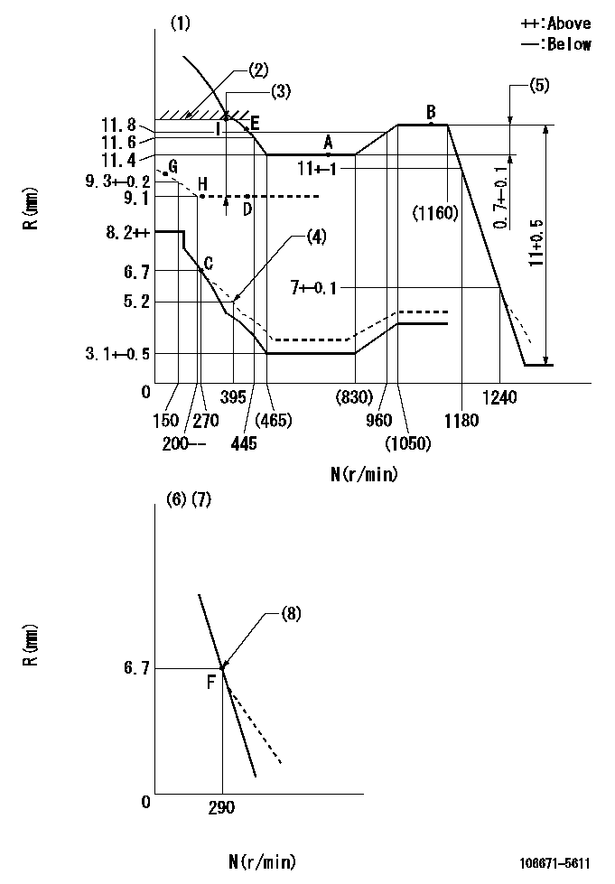
N:Pump speed
R:Rack position (mm)
(1)Tolerance for racks not indicated: +-0.05mm.
(2)Rack limit using stop lever: R1 (at N = N1)
(3)Boost compensator stroke: BCL
(4)Damper spring setting
(5)Rack difference between N = N2 and N = N3
(6)Variable speed specification: idling adjustment
(7)Fix the lever at the full-load position at delivery.
(8)Main spring setting
----------
R1=12.4+0.2mm N1=350r/min BCL=(3.4)mm N2=1100r/min N3=650r/min
----------
----------
R1=12.4+0.2mm N1=350r/min BCL=(3.4)mm N2=1100r/min N3=650r/min
----------
Speed control lever angle

F:Full speed
I:Idle
(1)Pump speed = aa
(2)Set the stopper bolt (fixed at full-load position at delivery.)
----------
aa=290r/min
----------
a=(16deg)+-5deg b=(7deg)+-5deg
----------
aa=290r/min
----------
a=(16deg)+-5deg b=(7deg)+-5deg
0000000901
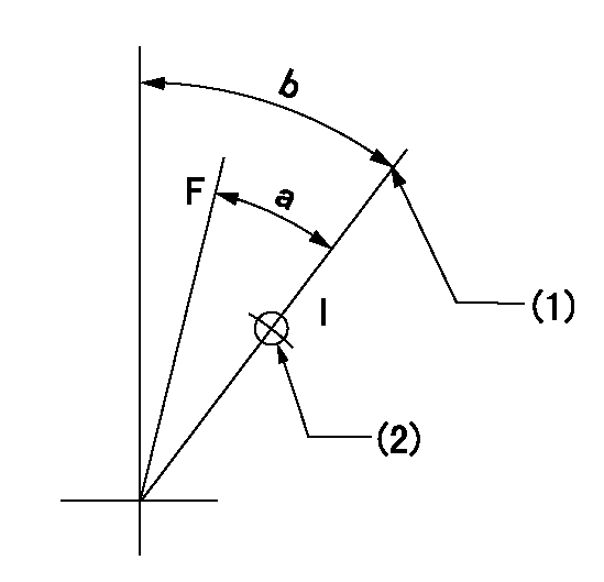
F:Full load
I:Idle
(1)Stopper bolt setting
(2)Use the hole at R = aa
----------
aa=42mm
----------
a=30.5deg+-3deg b=45deg+-5deg
----------
aa=42mm
----------
a=30.5deg+-3deg b=45deg+-5deg
Stop lever angle
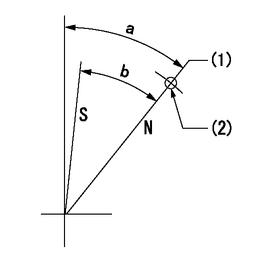
N:Pump normal
S:Stop the pump.
(1)Rack position aa (pump speed bb r/min )
(2)Use the pin above R = cc
----------
aa=12.4+0.2mm bb=350r/min cc=40mm
----------
a=41deg+-5deg b=41deg+-5deg
----------
aa=12.4+0.2mm bb=350r/min cc=40mm
----------
a=41deg+-5deg b=41deg+-5deg
Timing setting

(1)Pump vertical direction
(2)Coupling's key groove position at No 1 cylinder's beginning of injection
(3)-
(4)-
----------
----------
a=(20deg)
----------
----------
a=(20deg)
Information:
1. Loosen bolt (1).2. Loosen bolt (3).3. Push alternator (2) toward the engine to loosen the tension on the two alternator V-belts.4. Remove two alternator V-belts (4) from the alternator drive pulley and fan drive (6).5. Fasten a lifting strap and a hoist to fan drive (6). Remove four bolts (5) and the washers that hold the fan drive to the cylinder head assembly. Remove the fan drive. The weight of the fan drive is approximately 11 kg (25 lb). The following steps are for the installation of the fan drive.6. Be sure the mating surface on the cylinder head assembly and the mating surface on the fan drive support are thoroughly clean.7. Install the fan drive in the reverse order of removal.8. Adjust the tension of the alternator V-belts. See the topic "Alternator And Fan Drive Belts, Inspect/Adjust/Replace" in the 3114 & 3116 ATAAC Diesel Truck Engine Operation & Maintenance Manual, Form No. SEBU6723. Also, refer to the "Belt Tension Chart" in the 3114 & 3116 Diesel Truck Engines Specifications module, Form No. SENR6436.End By:a. install fan drive clutch assemblyDisassemble & Assemble Fan Drive
Start By:a. remove fan drive 1. Remove three bolts (6) and the washers. Access to bolts (6) can be made by rotating the fan pulley.2. Remove fan pulley assembly (2) from fan support (1).3. Remove two bolts (4) and thrust plate (5).4. Remove roller bearing assembly (8) and the bearing retainer from the fan pulley. Remove O-ring seal (7) from the bearing retainer. The following steps are for the assembly of the fan drive group.5. Be sure all parts of the fan drive group are thoroughly clean prior to assembly.6. Check the condition of O-ring seal (7) used in the bearing retainer. Also, check the condition of roller bearing assembly (8). If the components are damaged, use new parts for replacement.7. Install roller bearing assembly (8) in the bearing retainer. Be sure the lip seal in the roller bearing assembly is facing toward the bearing retainer.8. Install O-ring seal (7) in the bearing retainer. Put the bearing retainer and roller bearing assembly, as a unit, in position on pulley (2). Be sure the inner race of the roller bearing assembly in seated against the shoulder on the pulley.9. Install thrust plate (5) and two bolts (4).10. Put pulley assembly (2) in position in fan support (1). Install the three washers and bolts (6) that hold the unit together. Access to the mounting bolt holes can be made by rotating the fan pulley.11. Fill the bearing cavity in the fan drive with 30 g (1 oz) of 2S3230 Bearing Lubricant.End By:a. install fan drive
Start By:a. remove fan drive 1. Remove three bolts (6) and the washers. Access to bolts (6) can be made by rotating the fan pulley.2. Remove fan pulley assembly (2) from fan support (1).3. Remove two bolts (4) and thrust plate (5).4. Remove roller bearing assembly (8) and the bearing retainer from the fan pulley. Remove O-ring seal (7) from the bearing retainer. The following steps are for the assembly of the fan drive group.5. Be sure all parts of the fan drive group are thoroughly clean prior to assembly.6. Check the condition of O-ring seal (7) used in the bearing retainer. Also, check the condition of roller bearing assembly (8). If the components are damaged, use new parts for replacement.7. Install roller bearing assembly (8) in the bearing retainer. Be sure the lip seal in the roller bearing assembly is facing toward the bearing retainer.8. Install O-ring seal (7) in the bearing retainer. Put the bearing retainer and roller bearing assembly, as a unit, in position on pulley (2). Be sure the inner race of the roller bearing assembly in seated against the shoulder on the pulley.9. Install thrust plate (5) and two bolts (4).10. Put pulley assembly (2) in position in fan support (1). Install the three washers and bolts (6) that hold the unit together. Access to the mounting bolt holes can be made by rotating the fan pulley.11. Fill the bearing cavity in the fan drive with 30 g (1 oz) of 2S3230 Bearing Lubricant.End By:a. install fan drive