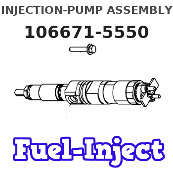
Information injection-pump assembly
BOSCH
9 400 616 863
9400616863
ZEXEL
106671-5550
1066715550
NISSAN-DIESEL
1679096604
1679096604
Rating:
Service parts 106671-5550 INJECTION-PUMP ASSEMBLY:
1.
_
7.
COUPLING PLATE
8.
_
9.
_
11.
Nozzle and Holder
16600-96609
12.
Open Pre:MPa(Kqf/cm2)
17.7{180}/22.6{230}
15.
NOZZLE SET
Include in #1:
106671-5550
as INJECTION-PUMP ASSEMBLY
Cross reference number
BOSCH
9 400 616 863
9400616863
ZEXEL
106671-5550
1066715550
NISSAN-DIESEL
1679096604
1679096604
Zexel num
Bosch num
Firm num
Name
106671-5550
9 400 616 863
1679096604 NISSAN-DIESEL
INJECTION-PUMP ASSEMBLY
PF6TA * K
PF6TA * K
Calibration Data:
Adjustment conditions
Test oil
1404 Test oil ISO4113 or {SAEJ967d}
1404 Test oil ISO4113 or {SAEJ967d}
Test oil temperature
degC
40
40
45
Nozzle and nozzle holder
105780-8140
Bosch type code
EF8511/9A
Nozzle
105780-0000
Bosch type code
DN12SD12T
Nozzle holder
105780-2080
Bosch type code
EF8511/9
Opening pressure
MPa
17.2
Opening pressure
kgf/cm2
175
Injection pipe
Outer diameter - inner diameter - length (mm) mm 8-3-600
Outer diameter - inner diameter - length (mm) mm 8-3-600
Overflow valve
134424-0020
Overflow valve opening pressure
kPa
157
123
191
Overflow valve opening pressure
kgf/cm2
1.6
1.25
1.95
Tester oil delivery pressure
kPa
157
157
157
Tester oil delivery pressure
kgf/cm2
1.6
1.6
1.6
Direction of rotation (viewed from drive side)
Right R
Right R
Injection timing adjustment
Direction of rotation (viewed from drive side)
Right R
Right R
Injection order
1-4-2-6-
3-5
Pre-stroke
mm
3.9
3.85
3.95
Beginning of injection position
Drive side NO.1
Drive side NO.1
Difference between angles 1
Cal 1-4 deg. 60 59.5 60.5
Cal 1-4 deg. 60 59.5 60.5
Difference between angles 2
Cyl.1-2 deg. 120 119.5 120.5
Cyl.1-2 deg. 120 119.5 120.5
Difference between angles 3
Cal 1-6 deg. 180 179.5 180.5
Cal 1-6 deg. 180 179.5 180.5
Difference between angles 4
Cal 1-3 deg. 240 239.5 240.5
Cal 1-3 deg. 240 239.5 240.5
Difference between angles 5
Cal 1-5 deg. 300 299.5 300.5
Cal 1-5 deg. 300 299.5 300.5
Injection quantity adjustment
Adjusting point
A
Rack position
11.3
Pump speed
r/min
700
700
700
Average injection quantity
mm3/st.
179.5
177.5
181.5
Max. variation between cylinders
%
0
-4
4
Basic
*
Fixing the lever
*
Boost pressure
kPa
86.6
86.6
Boost pressure
mmHg
650
650
Injection quantity adjustment_02
Adjusting point
D
Rack position
6+-0.5
Pump speed
r/min
300
300
300
Average injection quantity
mm3/st.
11.5
10.5
12.5
Max. variation between cylinders
%
0
-10
10
Fixing the rack
*
Boost pressure
kPa
0
0
0
Boost pressure
mmHg
0
0
0
Boost compensator adjustment
Pump speed
r/min
500
500
500
Rack position
9.3
Boost pressure
kPa
6.7
1.4
12
Boost pressure
mmHg
50
10
90
Boost compensator adjustment_02
Pump speed
r/min
500
500
500
Rack position
(11.3)
Boost pressure
kPa
77.3
74.6
80
Boost pressure
mmHg
580
560
600
Timer adjustment
Pump speed
r/min
750--
Advance angle
deg.
0
0
0
Remarks
Start
Start
Timer adjustment_02
Pump speed
r/min
700
Advance angle
deg.
0.5
Timer adjustment_03
Pump speed
r/min
1050
Advance angle
deg.
2
1.5
2.5
Remarks
Finish
Finish
Test data Ex:
Governor adjustment
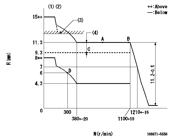
N:Pump speed
R:Rack position (mm)
(1)Adjust with speed control lever at full position (minimum-maximum speed specification)
(2)Target notch: K
(3)Boost compensator excessive fuel lever at operation: L1 (at 0 boost pressure)
(4)Boost compensator stroke: BCL
----------
K=16 L1=12.5+0.2mm BCL=(2)mm
----------
----------
K=16 L1=12.5+0.2mm BCL=(2)mm
----------
Speed control lever angle

F:Full speed
----------
----------
a=7deg+-5deg
----------
----------
a=7deg+-5deg
0000000901
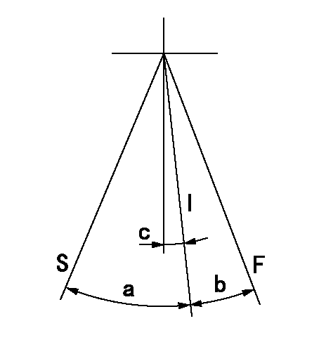
F:Full load
I:Idle
S:Stop
----------
----------
a=26deg+-3deg b=22deg+-5deg c=2deg+-5deg
----------
----------
a=26deg+-3deg b=22deg+-5deg c=2deg+-5deg
0000001101
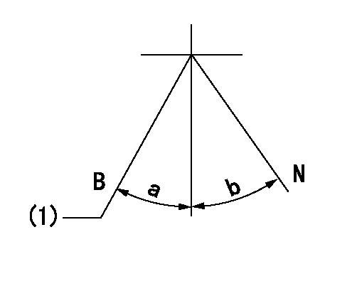
N:Normal
B:When boosted
(1)Rack position = aa at boost pressure 0.
----------
aa=12.5+0.2mm
----------
a=(17deg) b=(18deg)
----------
aa=12.5+0.2mm
----------
a=(17deg) b=(18deg)
Timing setting

(1)Pump vertical direction
(2)Coupling's key groove position at No 1 cylinder's beginning of injection
(3)-
(4)-
----------
----------
a=(20deg)
----------
----------
a=(20deg)
Information:
Start By:a. remove cylinder head assemblyb. remove front housing groupc. remove flywheel housingd. remove crankshaft rear seal assemblye. remove piston and connecting rod assemblies 1. Remove bolts (1). Remove main bearing caps (2). Remove thrust bearings (3) from the center main. Main bearing caps are identified by numbers one through seven. Unmarked caps should be marked by stamping the appropriate number toward the right side on the bottom prior to the removal. 2. Install a suitable size bolt in each end of the crankshaft as shown. Fasten two lifting straps (4) to the bolts in the crankshaft and to a hoist as shown. Carefully, remove the crankshaft. The appropriate weight of the crankshaft is 129 kg (285 lb).3. Remove the upper portions of the main bearings. The following steps are for the installation of the crankshaft.
Be sure the main bearing tabs engage with the grooves in the block and cap.
4. Position the upper portion of the main bearings in the cylinder block. Lower the main bearing portion in caps (2). Be sure everything is clean and only the bearing face is lubricated with clean engine oil.5. Fasten a hoist to the crankshaft, and position it in the cylinder block. 6. Install thrust bearings (3).7. Install main bearing caps (2) with the part numbers toward the right hand side of the cylinder block. Take care to ensure the caps are numbered one through seven from the front of the engine. Put clean engine oil or molylube on the bolt threads and the washer face; then install bolts (1). Tighten the bolts on the side where the main bearing tabs are located to a torque of 95 5 N m (70 4 lb ft). Tighten the bolts on the opposite side to a torque of 95 5 N m (70 4 lb ft).8. Put a mark on each bolt head and the bearing caps. Turn the bolts that are opposite the main bearing tabs an additional 90° 5° turn. Then turn the bolts on the side where the main bearing tabs are located an additional 90° 5° turn.
Typical Example9. Use tooling (A) to measure crankshaft end play. The crankshaft end play must be 0.10 to 0.50 mm (.004 to .020 in).End By:a. install piston and connecting rod assembliesb. install crankshaft rear seal assemblyc. install flywheel housingd. install front housing groupe. install cylinder head assembly
Have questions with 106671-5550?
Group cross 106671-5550 ZEXEL
Nissan-Diesel
Nissan-Diesel
Nissan-Diesel
106671-5550
9 400 616 863
1679096604
INJECTION-PUMP ASSEMBLY
PF6TA
PF6TA