Information injection-pump assembly
BOSCH
9 400 610 863
9400610863
ZEXEL
106671-5521
1066715521
NISSAN-DIESEL
1671396966
1671396966
Rating:
Service parts 106671-5521 INJECTION-PUMP ASSEMBLY:
1.
_
7.
COUPLING PLATE
8.
_
9.
_
11.
Nozzle and Holder
16600-96520
12.
Open Pre:MPa(Kqf/cm2)
22.6{230}

15.
NOZZLE SET
Include in #1:
106671-5521
as INJECTION-PUMP ASSEMBLY
Cross reference number
BOSCH
9 400 610 863
9400610863
ZEXEL
106671-5521
1066715521
NISSAN-DIESEL
1671396966
1671396966
Zexel num
Bosch num
Firm num
Name
106671-5521
9 400 610 863
1671396966 NISSAN-DIESEL
INJECTION-PUMP ASSEMBLY
PE6T * K 14CA INJECTION PUMP ASSY PE6P,6PD PE
PE6T * K 14CA INJECTION PUMP ASSY PE6P,6PD PE
Calibration Data:
Adjustment conditions
Test oil
1404 Test oil ISO4113 or {SAEJ967d}
1404 Test oil ISO4113 or {SAEJ967d}
Test oil temperature
degC
40
40
45
Nozzle and nozzle holder
105780-8140
Bosch type code
EF8511/9A
Nozzle
105780-0000
Bosch type code
DN12SD12T
Nozzle holder
105780-2080
Bosch type code
EF8511/9
Opening pressure
MPa
17.2
Opening pressure
kgf/cm2
175
Injection pipe
Outer diameter - inner diameter - length (mm) mm 8-3-600
Outer diameter - inner diameter - length (mm) mm 8-3-600
Overflow valve
132424-0620
Overflow valve opening pressure
kPa
157
123
191
Overflow valve opening pressure
kgf/cm2
1.6
1.25
1.95
Tester oil delivery pressure
kPa
157
157
157
Tester oil delivery pressure
kgf/cm2
1.6
1.6
1.6
Direction of rotation (viewed from drive side)
Right R
Right R
Injection timing adjustment
Direction of rotation (viewed from drive side)
Right R
Right R
Injection order
1-4-2-6-
3-5
Pre-stroke
mm
3.65
3.6
3.7
Beginning of injection position
Drive side NO.1
Drive side NO.1
Difference between angles 1
Cal 1-4 deg. 60 59.5 60.5
Cal 1-4 deg. 60 59.5 60.5
Difference between angles 2
Cyl.1-2 deg. 120 119.5 120.5
Cyl.1-2 deg. 120 119.5 120.5
Difference between angles 3
Cal 1-6 deg. 180 179.5 180.5
Cal 1-6 deg. 180 179.5 180.5
Difference between angles 4
Cal 1-3 deg. 240 239.5 240.5
Cal 1-3 deg. 240 239.5 240.5
Difference between angles 5
Cal 1-5 deg. 300 299.5 300.5
Cal 1-5 deg. 300 299.5 300.5
Injection quantity adjustment
Adjusting point
A
Rack position
11.7
Pump speed
r/min
650
650
650
Average injection quantity
mm3/st.
157
155
159
Max. variation between cylinders
%
0
-4
4
Basic
*
Fixing the lever
*
Boost pressure
kPa
86.6
86.6
Boost pressure
mmHg
650
650
Injection quantity adjustment_02
Adjusting point
C
Rack position
8.1+-0.5
Pump speed
r/min
250
250
250
Average injection quantity
mm3/st.
15
14
16
Max. variation between cylinders
%
0
-10
10
Fixing the rack
*
Boost pressure
kPa
0
0
0
Boost pressure
mmHg
0
0
0
Boost compensator adjustment
Pump speed
r/min
400
400
400
Rack position
10.1
Boost pressure
kPa
30
28.7
31.3
Boost pressure
mmHg
225
215
235
Boost compensator adjustment_02
Pump speed
r/min
400
400
400
Rack position
12.2+0.2
Boost pressure
kPa
73.3
73.3
73.3
Boost pressure
mmHg
550
550
550
Timer adjustment
Pump speed
r/min
1155++
Advance angle
deg.
0
0
0
Remarks
Do not advance until starting N = 1155.
Do not advance until starting N = 1155.
Timer adjustment_02
Pump speed
r/min
1155
Advance angle
deg.
0.5
Timer adjustment_03
Pump speed
r/min
-
Advance angle
deg.
2
2
2
Remarks
Measure the actual speed, stop
Measure the actual speed, stop
Test data Ex:
Governor adjustment
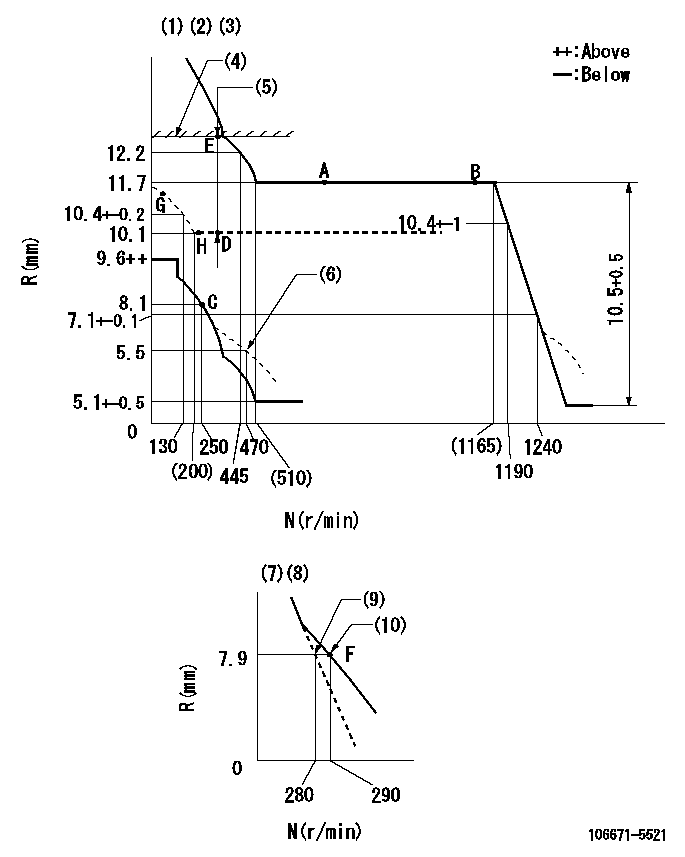
N:Pump speed
R:Rack position (mm)
(1)Lever ratio: RT
(2)Target shim dimension: TH
(3)Tolerance for racks not indicated: +-0.05mm.
(4)Rack limit using the stop lever: R1
(5)Boost compensator stroke: BCL
(6)Damper spring setting
(7)Variable speed specification: idling adjustment
(8)Fix the lever at the full-load position at delivery.
(9)Main spring setting
(10)Set idle sub-spring
----------
RT=1 TH=1.7mm R1=12.2+0.2mm BCL=(2.2)mm
----------
----------
RT=1 TH=1.7mm R1=12.2+0.2mm BCL=(2.2)mm
----------
Speed control lever angle

F:Full speed
I:Idle
(1)Set the pump speed at aa
(2)Set the stopper bolt (fixed at full-load position at delivery.)
----------
aa=290r/min
----------
a=(26.5deg)+-5deg b=(17deg)+-5deg
----------
aa=290r/min
----------
a=(26.5deg)+-5deg b=(17deg)+-5deg
0000000901

F:Full load
I:Idle
(1)Stopper bolt setting
(2)At center of threaded hole above R = aa
----------
aa=17mm
----------
a=15deg+-5deg b=25deg+-3deg
----------
aa=17mm
----------
a=15deg+-5deg b=25deg+-3deg
Stop lever angle
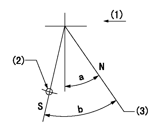
N:Pump normal
S:Stop the pump.
(1)Use the hole at R = aa
(2)Drive side
(3)Rack position bb
----------
aa=50mm bb=12.2+0.2mm
----------
a=30deg+-5deg b=32deg+-5deg
----------
aa=50mm bb=12.2+0.2mm
----------
a=30deg+-5deg b=32deg+-5deg
Timing setting

(1)Pump vertical direction
(2)Coupling's key groove position at No 1 cylinder's beginning of injection
(3)-
(4)-
----------
----------
a=(20deg)
----------
----------
a=(20deg)
Information:
1. Remove cylinder head assembly mounting bolts (1) and (2).
To prevent damage to the cylinder head assembly-to-spacer block dowels, keep the head assembly level during removal.
2. Fasten a hoist to the cylinder head assembly as shown. Lift the cylinder head assembly off of the spacer block. The approximate weight of the cylinder head is 236 kg (520 lb).3. Remove the cylinder head assembly gasket from the spacer block. The following steps are for the installation of the cylinder head assembly.4. Thoroughly clean the mating surfaces of the cylinder head assembly and the spacer block.5. Install the head gasket on the spacer block.6. Fasten a hoist to the cylinder head assembly. Position the cylinder head assembly on the dowels in the spacer block. Lower the cylinder head assembly onto the spacer block.7. Put clean engine oil on the threads of bolts (1) and (2) that hold the cylinder head assembly in position. Install bolts (1) and (2).
Cylinder Head Assembly Tightening Sequence8. Tighten cylinder head assembly mounting bolts (1) and (2) as follows:a. Put 2P2506 Thread Lubricant on the threads of bolts (1) and (2).b . Tighten bolts 1 through 26 in numerical sequence shown to a torque of 150 15 N m (110 11 lb ft).c. Tighten bolts 1 through 26 in numerical sequence shown to a torque of 275 15 N m (200 11 lb ft).d. Retorque bolts 1 through 26 in numerical sequence shown to 275 15 N m (200 11 lb ft).e. Tighten bolts 27 through 33 in numerical sequence shown to a torque of 25 7 N m (18 5 lb ft).End By:a. install valve cover baseb. install (EUI) fuel injectorsc. install rocker arm assemblies and push rodsd. install water outlet manifolde. install exhaust manifold
Have questions with 106671-5521?
Group cross 106671-5521 ZEXEL
Nissan-Diesel
Nissan-Diesel
106671-5521
9 400 610 863
1671396966
INJECTION-PUMP ASSEMBLY
PE6T
PE6T