Information injection-pump assembly
ZEXEL
106671-5520
1066715520
Rating:
Service parts 106671-5520 INJECTION-PUMP ASSEMBLY:
1.
_
7.
COUPLING PLATE
8.
_
9.
_
11.
Nozzle and Holder
16600-96520
12.
Open Pre:MPa(Kqf/cm2)
22.6{230}

15.
NOZZLE SET
Include in #1:
106671-5520
as INJECTION-PUMP ASSEMBLY
Cross reference number
ZEXEL
106671-5520
1066715520
Zexel num
Bosch num
Firm num
Name
106671-5520
INJECTION-PUMP ASSEMBLY
Calibration Data:
Adjustment conditions
Test oil
1404 Test oil ISO4113 or {SAEJ967d}
1404 Test oil ISO4113 or {SAEJ967d}
Test oil temperature
degC
40
40
45
Nozzle and nozzle holder
105780-8140
Bosch type code
EF8511/9A
Nozzle
105780-0000
Bosch type code
DN12SD12T
Nozzle holder
105780-2080
Bosch type code
EF8511/9
Opening pressure
MPa
17.2
Opening pressure
kgf/cm2
175
Injection pipe
Outer diameter - inner diameter - length (mm) mm 8-3-600
Outer diameter - inner diameter - length (mm) mm 8-3-600
Overflow valve
132424-0620
Overflow valve opening pressure
kPa
157
123
191
Overflow valve opening pressure
kgf/cm2
1.6
1.25
1.95
Tester oil delivery pressure
kPa
157
157
157
Tester oil delivery pressure
kgf/cm2
1.6
1.6
1.6
Direction of rotation (viewed from drive side)
Right R
Right R
Injection timing adjustment
Direction of rotation (viewed from drive side)
Right R
Right R
Injection order
1-4-2-6-
3-5
Pre-stroke
mm
3.65
3.6
3.7
Beginning of injection position
Drive side NO.1
Drive side NO.1
Difference between angles 1
Cal 1-4 deg. 60 59.5 60.5
Cal 1-4 deg. 60 59.5 60.5
Difference between angles 2
Cyl.1-2 deg. 120 119.5 120.5
Cyl.1-2 deg. 120 119.5 120.5
Difference between angles 3
Cal 1-6 deg. 180 179.5 180.5
Cal 1-6 deg. 180 179.5 180.5
Difference between angles 4
Cal 1-3 deg. 240 239.5 240.5
Cal 1-3 deg. 240 239.5 240.5
Difference between angles 5
Cal 1-5 deg. 300 299.5 300.5
Cal 1-5 deg. 300 299.5 300.5
Injection quantity adjustment
Adjusting point
A
Rack position
11.7
Pump speed
r/min
650
650
650
Average injection quantity
mm3/st.
157
155
159
Max. variation between cylinders
%
0
-4
4
Basic
*
Fixing the lever
*
Boost pressure
kPa
64
64
Boost pressure
mmHg
480
480
Injection quantity adjustment_02
Adjusting point
C
Rack position
8.1+-0.5
Pump speed
r/min
250
250
250
Average injection quantity
mm3/st.
15
14
16
Max. variation between cylinders
%
0
-10
10
Fixing the rack
*
Boost pressure
kPa
0
0
0
Boost pressure
mmHg
0
0
0
Boost compensator adjustment
Pump speed
r/min
400
400
400
Rack position
11.1
Boost pressure
kPa
30
28.7
31.3
Boost pressure
mmHg
225
215
235
Boost compensator adjustment_02
Pump speed
r/min
400
400
400
Rack position
12.2+0.2
Boost pressure
kPa
50.7
50.7
50.7
Boost pressure
mmHg
380
380
380
Timer adjustment
Pump speed
r/min
1155++
Advance angle
deg.
0
0
0
Remarks
Do not advance until starting N = 1155.
Do not advance until starting N = 1155.
Timer adjustment_02
Pump speed
r/min
1155
Advance angle
deg.
0.5
Timer adjustment_03
Pump speed
r/min
-
Advance angle
deg.
2
2
2
Remarks
Measure the actual speed, stop
Measure the actual speed, stop
Test data Ex:
Governor adjustment
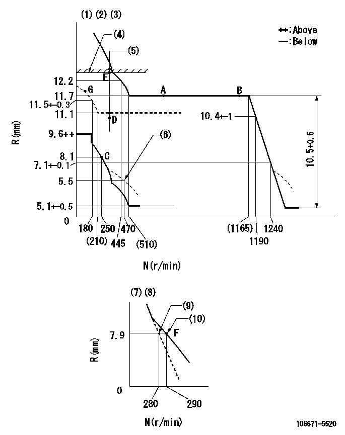
N:Pump speed
R:Rack position (mm)
(1)Lever ratio: RT
(2)Target shim dimension: TH
(3)Tolerance for racks not indicated: +-0.05mm.
(4)Rack limit using the stop lever: R1
(5)Boost compensator stroke: BCL
(6)Damper spring setting
(7)Variable speed specification: idling adjustment
(8)Fix the lever at the full-load position at delivery.
(9)Main spring setting
(10)Set idle sub-spring
----------
RT=1 TH=1.7mm R1=12.2+0.2mm BCL=(1.2)mm
----------
----------
RT=1 TH=1.7mm R1=12.2+0.2mm BCL=(1.2)mm
----------
Speed control lever angle

F:Full speed
I:Idle
(1)Set the pump speed at aa
(2)Set the stopper bolt (fixed at full-load position at delivery.)
----------
aa=290r/min
----------
a=(26.5deg)+-5deg b=(17deg)+-5deg
----------
aa=290r/min
----------
a=(26.5deg)+-5deg b=(17deg)+-5deg
0000000901

F:Full load
I:Idle
(1)Stopper bolt setting
(2)At center of threaded hole above R = aa
----------
aa=17mm
----------
a=15deg+-5deg b=25deg+-3deg
----------
aa=17mm
----------
a=15deg+-5deg b=25deg+-3deg
Stop lever angle
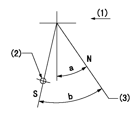
N:Pump normal
S:Stop the pump.
(1)Use the hole at R = aa
(2)Drive side
(3)Rack position bb
----------
aa=50mm bb=12.2+0.2mm
----------
a=30deg+-5deg b=32deg+-5deg
----------
aa=50mm bb=12.2+0.2mm
----------
a=30deg+-5deg b=32deg+-5deg
Timing setting

(1)Pump vertical direction
(2)Coupling's key groove position at No 1 cylinder's beginning of injection
(3)-
(4)-
----------
----------
a=(20deg)
----------
----------
a=(20deg)
Information:
1. Disconnect wires (1) from the Jake Brake. Remove three bolts (2) and two nuts (3). Remove the Jake Brake. 2. Remove the Jake Brake exhaust bridge assemblies (4). The following steps are for the installation of the Jake Brake.3. Put Jake Brake exhaust bridge assemblies (4) in the same positions shown in Photo C52074P1.4. Position the Jake Brake assembly, and install three bolts (2) and two nuts (3) that hold it. Tighten three bolts (2) to a torque of 55 10 N m (41 7 lb ft). Tighten two nuts (3) to a torque of 80 15 N m (59 11 lb ft).5. Connect wires (1) to the Jake Brake.End By:a. install valve cover assembliesDisassemble & Assemble Jake Brake
Start By:a. remove Jake Brake (An Attachment) 1. Apply finger pressure to control valve cover (6). Remove retaining ring (7). Release finger pressure slowly. Remove control valve cover (6), insert (5), spring (4), spring (3), collar (2) and control valve (1). 2. Remove solenoid (8). Remove three O-ring seals (9) from the solenoid. 3. Remove locknut (11). Back out adjusting screw (10) until the slave piston is fully retracted. 4. Using a suitable size clamp, compress retainer (15) until it is 1mm (.039 in) below the retaining ring groove. Using suitable size snap ring pliers, remove retaining ring (16). Slowly loosen the clamp to release the spring pressure against retainer (15), springs (14) and (13) and slave piston (12). 5. Using suitable snap ring pliers, remove retaining ring (20). Remove retainer (19), spring (18) and master piston assembly (17). The following steps are for the assembly of the Jake Brake.6. Check the condition of the master piston assembly (17). The master piston assembly must be free of score and wear marks.7. Install master piston assembly (17), spring (18), retainer (19) and retaining ring (20).8. Install slave piston (12), springs (13) and (14) and retainer (15). Clamp and compress and slave piston retainer until it is 1 mm (.039 in) below the retaining ring groove. Install retaining ring (16). Release the clamp. Be sure retainer (15) is seated properly.9. Screw adjusting screw (10) in until it makes contact with the slave piston. Install locknut (11) on the screw.
Be sure O-ring seals (9) are seated on solenoid (8). Do not twist or unseat the O-ring seals during installation of the solenoid.
10. Check the condition of the O-ring seals (9) used on solenoid (8). If the seals are worn or damaged, use new parts for replacement. Install three O-ring seals (9) on solenoid valve (8). Install solenoid valve (8), and tighten it to a torque of 7 N m (60 lb in).11. Install control valve (1). Install collar (2) with the longer sleeve area facing up. Install springs (3) and (4) and insert (5). Install control valve cover (6). Install retaining ring (7). Rotate the retaining ring so the retaining ring ears are located away from the slot in the housing. Release finger pressure. For assembly adjustments of
Have questions with 106671-5520?
Group cross 106671-5520 ZEXEL
Nissan-Diesel
106671-5520
INJECTION-PUMP ASSEMBLY