Information injection-pump assembly
BOSCH
9 400 610 859
9400610859
ZEXEL
106671-5480
1066715480
NISSAN-DIESEL
1671396963
1671396963
Rating:
Service parts 106671-5480 INJECTION-PUMP ASSEMBLY:
1.
_
7.
COUPLING PLATE
8.
_
9.
_
11.
Nozzle and Holder
16600-96610
12.
Open Pre:MPa(Kqf/cm2)
22.6{230}
15.
NOZZLE SET
Include in #1:
106671-5480
as INJECTION-PUMP ASSEMBLY
Cross reference number
BOSCH
9 400 610 859
9400610859
ZEXEL
106671-5480
1066715480
NISSAN-DIESEL
1671396963
1671396963
Zexel num
Bosch num
Firm num
Name
106671-5480
9 400 610 859
1671396963 NISSAN-DIESEL
INJECTION-PUMP ASSEMBLY
PF6TA K 14CA INJECTION PUMP ASSY PE6P,6PD PE
PF6TA K 14CA INJECTION PUMP ASSY PE6P,6PD PE
Calibration Data:
Adjustment conditions
Test oil
1404 Test oil ISO4113 or {SAEJ967d}
1404 Test oil ISO4113 or {SAEJ967d}
Test oil temperature
degC
40
40
45
Nozzle and nozzle holder
105780-8140
Bosch type code
EF8511/9A
Nozzle
105780-0000
Bosch type code
DN12SD12T
Nozzle holder
105780-2080
Bosch type code
EF8511/9
Opening pressure
MPa
17.2
Opening pressure
kgf/cm2
175
Injection pipe
Outer diameter - inner diameter - length (mm) mm 8-3-600
Outer diameter - inner diameter - length (mm) mm 8-3-600
Overflow valve
132424-0620
Overflow valve opening pressure
kPa
157
123
191
Overflow valve opening pressure
kgf/cm2
1.6
1.25
1.95
Tester oil delivery pressure
kPa
157
157
157
Tester oil delivery pressure
kgf/cm2
1.6
1.6
1.6
Direction of rotation (viewed from drive side)
Right R
Right R
Injection timing adjustment
Direction of rotation (viewed from drive side)
Right R
Right R
Injection order
1-4-2-6-
3-5
Pre-stroke
mm
3.9
3.85
3.95
Beginning of injection position
Drive side NO.1
Drive side NO.1
Difference between angles 1
Cal 1-4 deg. 60 59.5 60.5
Cal 1-4 deg. 60 59.5 60.5
Difference between angles 2
Cyl.1-2 deg. 120 119.5 120.5
Cyl.1-2 deg. 120 119.5 120.5
Difference between angles 3
Cal 1-6 deg. 180 179.5 180.5
Cal 1-6 deg. 180 179.5 180.5
Difference between angles 4
Cal 1-3 deg. 240 239.5 240.5
Cal 1-3 deg. 240 239.5 240.5
Difference between angles 5
Cal 1-5 deg. 300 299.5 300.5
Cal 1-5 deg. 300 299.5 300.5
Injection quantity adjustment
Adjusting point
A
Rack position
10.7
Pump speed
r/min
600
600
600
Average injection quantity
mm3/st.
163
161
165
Max. variation between cylinders
%
0
-4
4
Basic
*
Fixing the lever
*
Boost pressure
kPa
66.7
66.7
Boost pressure
mmHg
500
500
Injection quantity adjustment_02
Adjusting point
D
Rack position
9.05
Pump speed
r/min
400
400
400
Average injection quantity
mm3/st.
116
113
119
Fixing the lever
*
Boost pressure
kPa
0
0
0
Boost pressure
mmHg
0
0
0
Injection quantity adjustment_03
Adjusting point
E
Rack position
6+-0.5
Pump speed
r/min
260
260
260
Average injection quantity
mm3/st.
14.5
13.2
15.8
Max. variation between cylinders
%
0
-10
10
Fixing the rack
*
Boost pressure
kPa
0
0
0
Boost pressure
mmHg
0
0
0
Boost compensator adjustment
Pump speed
r/min
400
400
400
Rack position
9.05
Boost pressure
kPa
13.3
12
14.6
Boost pressure
mmHg
100
90
110
Boost compensator adjustment_02
Pump speed
r/min
400
400
400
Rack position
11.2+0.2
Boost pressure
kPa
53.3
53.3
53.3
Boost pressure
mmHg
400
400
400
Timer adjustment
Pump speed
r/min
-
Advance angle
deg.
0
0
0
Remarks
Measure speed (beginning of operation).
Measure speed (beginning of operation).
Timer adjustment_02
Pump speed
r/min
-
Advance angle
deg.
1
0.5
1.5
Remarks
Measure the actual speed, stop
Measure the actual speed, stop
Test data Ex:
Governor adjustment
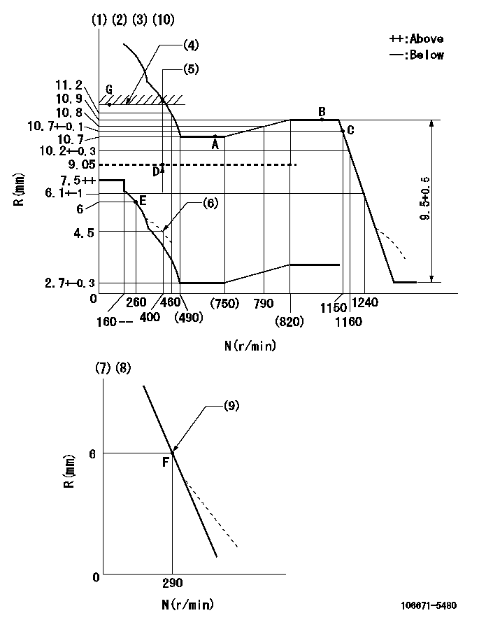
N:Pump speed
R:Rack position (mm)
(1)Lever ratio: RT
(2)Target shim dimension: TH
(3)Tolerance for racks not indicated: +-0.05mm.
(4)Rack limit using the stop lever: R1
(5)Boost compensator stroke: BCL
(6)Damper spring setting
(7)Variable speed specification: idling adjustment
(8)Fix the lever at the full-load position at delivery.
(9)Main spring setting
(10)Perform governor adjustment at an ambient temperature of at least 15 deg C (boost compensator start spring is shape memory alloy).
----------
RT=1 TH=2.2mm R1=11.2+0.2mm BCL=(2.25)mm
----------
----------
RT=1 TH=2.2mm R1=11.2+0.2mm BCL=(2.25)mm
----------
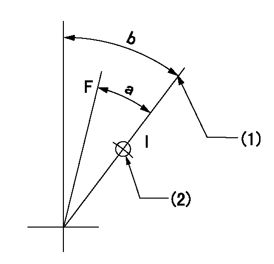
Speed control lever angle

F:Full speed
I:Idle
(1)Pump speed = aa
(2)Set the stopper bolt (fixed at full-load position at delivery.)
----------
aa=290r/min
----------
a=14deg+-5deg b=4deg+-5deg
----------
aa=290r/min
----------
a=14deg+-5deg b=4deg+-5deg
0000000901
F:Full load
I:Idle
(1)Stopper bolt setting
(2)Use the hole at R = aa
----------
aa=42mm
----------
a=29.5deg+-3deg b=45deg+-5deg
----------
aa=42mm
----------
a=29.5deg+-3deg b=45deg+-5deg
Stop lever angle
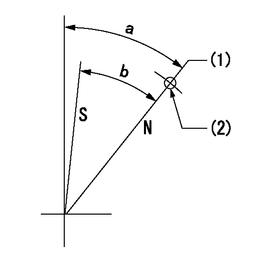
N:Pump normal
S:Stop the pump.
(1)Rack position = aa
(2)Use the pin at R = bb
----------
aa=11.2+0.2mm bb=40mm
----------
a=37.5deg+-5deg b=35.5deg+-5deg
----------
aa=11.2+0.2mm bb=40mm
----------
a=37.5deg+-5deg b=35.5deg+-5deg
Timing setting

(1)Pump vertical direction
(2)Coupling's key groove position at No 1 cylinder's beginning of injection
(3)-
(4)-
----------
----------
a=(20deg)
----------
----------
a=(20deg)
Information:
Grounding Practices
Proper grounding for vehicle and engine electrical systems is necessary for proper vehicle performance and reliability. Improper grounding will result in uncontrolled and unreliable electrical circuit paths.Uncontrolled engine electrical circuit paths can result in damage to main bearings, crankshaft journal surfaces, and aluminum components.Uncontrolled electrical circuit paths can cause electrical noise which may degrade vehicle and radio performance.To insure proper functioning of the vehicle and engine electrical systems, an engine-to-frame ground strap with a direct path to the battery must be used. This may be provided by way of a starter motor ground, a frame to starter motor ground, or a direct frame to engine ground.In any case, an engine-to-frame ground strap must be run from the cylinder head grounding stud to the frame and negative battery post.
Cylinder Head-To-Battery (-) Ground
Alternate Cylinder Head-To-Battery (-) GroundThe cylinder head must have a wire ground to battery as shown in the above illustrations.Ground wires/straps should be combined at ground studs dedicated for ground use only. At "Every 12,500 miles (20 125 km) or 250 hours," Inspect/Check all engine grounds. All grounds should be tight and free of corrosion.All ground paths must be capable of carrying any conceivable fault currents, and an awg # 0 or larger wire is recommended for the cylinder head grounding strap.The engine alternator should be battery (-) grounded with a wire size adequate to handle full alternator charging current.
When boost starting an engine, follow the instructions in "Engine Starting" in the "Operation Section" to properly start the engine.This engine may be equipped with a 12 or 24 volt starting system. Use only equal voltage for boost starting. The use of a welder or higher voltage will damage the electrical system.
The engine has several input components which are electronic. These components require an operating voltage.Unlike many electronic systems of the past, this engine is tolerant to common external sources of electrical noise, but electro-mechanical buzzers can cause disruptions in the power supply. If electro-mechanical buzzers are used anywhere on the vehicle, it is desirable to have the engine electronics (control group, throttle position sensor, and "check engine" lamp) powered directly from the battery system through a dedicated relay, and not through a common power bus with other key switch activated devices.Engine Electrical System
The electrical system can have three separate circuits: the charging circuit, the starting circuit and the low amperage circuit. Some of the electrical system components are used in more than one circuit. The battery (batteries), circuit breaker, ammeter, cables and wires from the battery are all common in each of the circuits.The charging circuit is in operation when the engine is running. An alternator makes electricity for the charging circuit. A voltage regulator in the circuit controls the electrical output to keep the battery at full charge.The starting circuit is in operation only when the start switch is activated.The low amperage circuit and the charging circuit are both connected through the ammeter. The starting circuit is not connected through the ammeter.Charging System Components
Alternator
The alternator is
Have questions with 106671-5480?
Group cross 106671-5480 ZEXEL
Nissan-Diesel
Nissan-Diesel
Nissan-Diesel
Nissan-Diesel
106671-5480
9 400 610 859
1671396963
INJECTION-PUMP ASSEMBLY
PF6TA
PF6TA