Information injection-pump assembly
BOSCH
F 01G 09U 07E
f01g09u07e
ZEXEL
106671-5390
1066715390
Rating:
Cross reference number
BOSCH
F 01G 09U 07E
f01g09u07e
ZEXEL
106671-5390
1066715390
Zexel num
Bosch num
Firm num
Name
Calibration Data:
Adjustment conditions
Test oil
1404 Test oil ISO4113 or {SAEJ967d}
1404 Test oil ISO4113 or {SAEJ967d}
Test oil temperature
degC
40
40
45
Nozzle and nozzle holder
105780-8250
Bosch type code
1 688 901 101
Nozzle
105780-0120
Bosch type code
1 688 901 990
Nozzle holder
105780-2190
Opening pressure
MPa
20.7
Opening pressure
kgf/cm2
211
Injection pipe
Outer diameter - inner diameter - length (mm) mm 8-3-600
Outer diameter - inner diameter - length (mm) mm 8-3-600
Overflow valve
131425-0120
Overflow valve opening pressure
kPa
157
123
191
Overflow valve opening pressure
kgf/cm2
1.6
1.25
1.95
Tester oil delivery pressure
kPa
255
255
255
Tester oil delivery pressure
kgf/cm2
2.6
2.6
2.6
RED3 control unit part number
407910-3
960
RED3 rack sensor specifications
mm
19
Direction of rotation (viewed from drive side)
Right R
Right R
Injection timing adjustment
Direction of rotation (viewed from drive side)
Right R
Right R
Injection order
1-4-2-6-
3-5
Pre-stroke
mm
4.4
4.37
4.43
Beginning of injection position
Drive side NO.1
Drive side NO.1
Difference between angles 1
Cal 1-4 deg. 60 59.75 60.25
Cal 1-4 deg. 60 59.75 60.25
Difference between angles 2
Cyl.1-2 deg. 120 119.75 120.25
Cyl.1-2 deg. 120 119.75 120.25
Difference between angles 3
Cal 1-6 deg. 180 179.75 180.25
Cal 1-6 deg. 180 179.75 180.25
Difference between angles 4
Cal 1-3 deg. 240 239.75 240.25
Cal 1-3 deg. 240 239.75 240.25
Difference between angles 5
Cal 1-5 deg. 300 299.75 300.25
Cal 1-5 deg. 300 299.75 300.25
Injection quantity adjustment
Rack position
(13.5)
Vist
V
1.82
1.82
1.82
Pump speed
r/min
650
650
650
Average injection quantity
mm3/st.
141.5
139.5
143.5
Max. variation between cylinders
%
0
-4
4
Basic
*
Injection quantity adjustment_02
Rack position
(8.4)
Vist
V
2.6
2.5
2.7
Pump speed
r/min
330
330
330
Average injection quantity
mm3/st.
15
14
16
Max. variation between cylinders
%
0
-10
10
Test data Ex:
Governor adjustment

(1)Adjusting range
(2)Step response time
(N): Speed of the pump
(L): Load
(theta) Advance angle
(Srd1) Step response time 1
(Srd2) Step response time 2
1. Adjusting conditions for the variable timer
(1)Adjust the clearance between the pickup and the protrusion to L.
----------
L=1-0.2mm N4=800r/min C4=(8)deg t1=2--sec. t2=2--sec.
----------
N1=400r/min N2=1000++r/min N3=1250r/min C1=8+-0.3deg C2=4++deg C3=4--deg P1=0kPa(0kgf/cm2) P2=147kPa(1.5kgf/cm2) P3=392kPa(4kgf/cm2) R01=0/4load R02=4/4load R03=4/4load
----------
L=1-0.2mm N4=800r/min C4=(8)deg t1=2--sec. t2=2--sec.
----------
N1=400r/min N2=1000++r/min N3=1250r/min C1=8+-0.3deg C2=4++deg C3=4--deg P1=0kPa(0kgf/cm2) P2=147kPa(1.5kgf/cm2) P3=392kPa(4kgf/cm2) R01=0/4load R02=4/4load R03=4/4load
Speed control lever angle
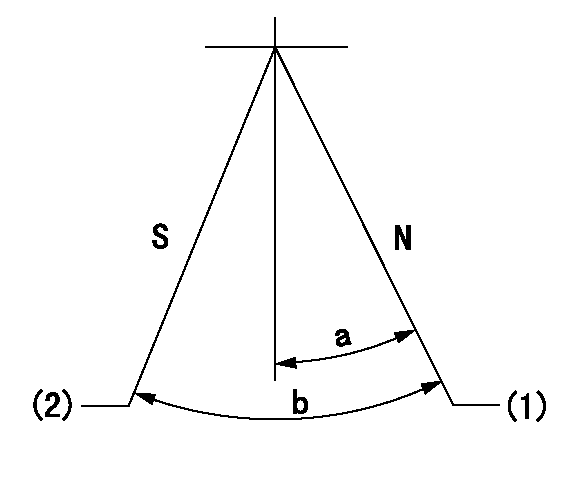
N:Pump normal
S:Stop the pump.
(1)Rack position = aa
(2)Rack position bb
----------
aa=20mm bb=1mm
----------
a=20deg+-5deg b=37deg+-5deg
----------
aa=20mm bb=1mm
----------
a=20deg+-5deg b=37deg+-5deg
0000000901

(1)Pump vertical direction
(2)Coupling's key groove position at No 1 cylinder's beginning of injection
(3)-
(4)-
----------
----------
a=(30deg)
----------
----------
a=(30deg)
Stop lever angle

(Rs) rack sensor specifications
(C/U) control unit part number
(V) Rack sensor output voltage
(R) Rack position (mm)
1. Confirming governor output characteristics (rack 19 mm, span 6 mm)
(1)When the output voltages of the rack sensor are V1 and V2, check that the rack positions R1 and R2 in the table above are satisfied.
----------
----------
----------
----------
Information:
High Gear RPM Limit:
Engine RPM Limit when vehicle speed is above "High Gear Turn On Speed". This is a "hard" limit: PEEC III will not power the engine above this limit. This is to encourage the driver to shift up into overdrive or top gear. Maximum 3,000 rpmMinimum 1,300 rpmDefault 3,000 rpmHigh Gear Turn On Speed:
Vehicle Speed where "High Gear RPM Limit" turns on. This must be matched to the specific drive train for best performance. Maximum 127 mphMinimum 30 mphDefault 127 mphEngine Parameters
Rating Number:
Number of rating within horsepower family. The personality module defines the horsepower family (such as 350 hp) and may contain several ratings within that family. The rating number defines which rating is used (such as 350 hp @ 1900 rpm or 330 hp @ 1700 rpm) within the family.Top Engine Limit:
Maximum engine RPM when the engine is under load. The engine will still achieve Rated RPM under no load conditions. Maximum Rated rpm + 20 rpmMinimum Rated rpm - 79 rpmDefault Rated rpm + 20 rpmLow Idle RPM:
Minimum engine RPM which may be programmed to any value between 600 RPM to 750 RPM range. Maximum 750 rpmMinimum 600 rpmDefault 750 rpmIdle Shutdown Time:
Time (in minutes) that engine will idle before shutting down (between 3 and 60 minutes). Engine will only shutdown if PEEC III sees no engine load, no vehicle speed, and the park brake is set. If this parameter is programmed to zero, this feature is disabled and the engine will idle until the key switch is turned OFF. Maximum 60 minMinimum 3 minDefault 0 minEngine Protection Parameters
Engine Protection Mode:
Determines the level of action taken by the ECM in response to a potentially engine damaging condition recognized by the Caterpillar Coolant Temperature, Oil Pressure, or OEM Coolant Level (if installed and enabled) Default Alternative OFFAlternative DERATEAlternative SHUTDOWNCoolant Level Sensor Enable/Disable:
Determines if the ECM monitors the Coolant Level Sensor inputs. Default ENABLEDAlternative DISABLEDPasswords
Factory Passwords
Factory passwords are required to perform each of the following four functions:1. Program a New ECM When an ECM is replaced, the System Configuration Parameters must be programmed into the new ECM. These parameters are protected by factory passwords.2. Rerate Engine to another Engine Family This requires changing the personality Module Code, which is protected by factory passwords.3. Read Customer Passwords If the owner loses his customer passwords, he will not be able to program customer parameters. Using factory passwords, one can read customer passwords, then use those customer passwords to program customer parameters.4. Clear Certain Diagnostic Codes Only Diagnostic Codes 190-00 (Engine Overspeed Warning) and 23-02 (Excessive Engine Power) require factory passwords to clear once they are logged. Certain other codes require customer passwords. The majority of logged codes require no passwords to clear.Since factory passwords contain alphabetic characters, only the ECAP may perform these functions. The DDT cannot because it hasn't any alphabetic character keys.To obtain factory passwords, proceed as if you already had the password. At some point, if factory passwords are truly needed, the ECAP will request