Information injection-pump assembly
BOSCH
9 400 610 853
9400610853
ZEXEL
106671-5381
1066715381
NISSAN-DIESEL
1680095503
1680095503
Rating:
Service parts 106671-5381 INJECTION-PUMP ASSEMBLY:
1.
_
7.
COUPLING PLATE
8.
_
9.
_
11.
Nozzle and Holder
16600-95505
12.
Open Pre:MPa(Kqf/cm2)
18.6{190}/22.6{230}
14.
NOZZLE
Include in #1:
106671-5381
as INJECTION-PUMP ASSEMBLY
Cross reference number
BOSCH
9 400 610 853
9400610853
ZEXEL
106671-5381
1066715381
NISSAN-DIESEL
1680095503
1680095503
Zexel num
Bosch num
Firm num
Name
9 400 610 853
1680095503 NISSAN-DIESEL
INJECTION-PUMP ASSEMBLY
NF6TA * K 14CA INJECTION PUMP ASSY PE6P,6PD PE
NF6TA * K 14CA INJECTION PUMP ASSY PE6P,6PD PE
Calibration Data:
Adjustment conditions
Test oil
1404 Test oil ISO4113 or {SAEJ967d}
1404 Test oil ISO4113 or {SAEJ967d}
Test oil temperature
degC
40
40
45
Nozzle and nozzle holder
105780-8140
Bosch type code
EF8511/9A
Nozzle
105780-0000
Bosch type code
DN12SD12T
Nozzle holder
105780-2080
Bosch type code
EF8511/9
Opening pressure
MPa
17.2
Opening pressure
kgf/cm2
175
Injection pipe
Outer diameter - inner diameter - length (mm) mm 8-3-600
Outer diameter - inner diameter - length (mm) mm 8-3-600
Overflow valve
134424-4120
Overflow valve opening pressure
kPa
255
221
289
Overflow valve opening pressure
kgf/cm2
2.6
2.25
2.95
Tester oil delivery pressure
kPa
157
157
157
Tester oil delivery pressure
kgf/cm2
1.6
1.6
1.6
Direction of rotation (viewed from drive side)
Right R
Right R
Injection timing adjustment
Direction of rotation (viewed from drive side)
Right R
Right R
Injection order
1-4-2-6-
3-5
Pre-stroke
mm
4.4
4.37
4.43
Beginning of injection position
Drive side NO.1
Drive side NO.1
Difference between angles 1
Cal 1-4 deg. 60 59.75 60.25
Cal 1-4 deg. 60 59.75 60.25
Difference between angles 2
Cyl.1-2 deg. 120 119.75 120.25
Cyl.1-2 deg. 120 119.75 120.25
Difference between angles 3
Cal 1-6 deg. 180 179.75 180.25
Cal 1-6 deg. 180 179.75 180.25
Difference between angles 4
Cal 1-3 deg. 240 239.75 240.25
Cal 1-3 deg. 240 239.75 240.25
Difference between angles 5
Cal 1-5 deg. 300 299.75 300.25
Cal 1-5 deg. 300 299.75 300.25
Injection quantity adjustment
Adjusting point
-
Rack position
13
Pump speed
r/min
650
650
650
Average injection quantity
mm3/st.
156.5
153.5
159.5
Max. variation between cylinders
%
0
-4
4
Basic
*
Fixing the rack
*
Standard for adjustment of the maximum variation between cylinders
*
Injection quantity adjustment_02
Adjusting point
Z
Rack position
8+-0.5
Pump speed
r/min
530
530
530
Average injection quantity
mm3/st.
10
9
11
Max. variation between cylinders
%
0
-10
10
Fixing the rack
*
Standard for adjustment of the maximum variation between cylinders
*
Injection quantity adjustment_03
Adjusting point
A
Rack position
R1(13)
Pump speed
r/min
650
650
650
Average injection quantity
mm3/st.
156.5
154.5
158.5
Basic
*
Fixing the lever
*
Boost pressure
kPa
46.7
46.7
Boost pressure
mmHg
350
350
Injection quantity adjustment_04
Adjusting point
B
Rack position
(R1+0.2)
Pump speed
r/min
1250
1250
1250
Average injection quantity
mm3/st.
127.5
121.5
133.5
Fixing the lever
*
Boost pressure
kPa
46.7
46.7
Boost pressure
mmHg
350
350
Injection quantity adjustment_05
Adjusting point
C
Rack position
R2(R1-1)
Pump speed
r/min
300
300
300
Average injection quantity
mm3/st.
149.5
143.5
155.5
Fixing the lever
*
Boost pressure
kPa
46.7
46.7
Boost pressure
mmHg
350
350
Injection quantity adjustment_06
Adjusting point
D
Rack position
R2-1.35
Pump speed
r/min
300
300
300
Average injection quantity
mm3/st.
81.5
75.5
87.5
Fixing the lever
*
Boost pressure
kPa
0
0
0
Boost pressure
mmHg
0
0
0
Boost compensator adjustment
Pump speed
r/min
300
300
300
Rack position
R2-1.35
Boost pressure
kPa
10.7
9.4
12
Boost pressure
mmHg
80
70
90
Boost compensator adjustment_02
Pump speed
r/min
300
300
300
Rack position
R2(R1-1)
Boost pressure
kPa
33.3
33.3
33.3
Boost pressure
mmHg
250
250
250
Test data Ex:
Governor adjustment
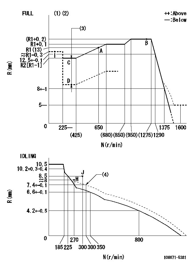
N:Pump speed
R:Rack position (mm)
(1)Torque cam stamping: T1
(2)Tolerance for racks not indicated: +-0.05mm.
(3)Boost compensator stroke: BCL
(4)Damper spring setting
----------
T1=AF12 BCL=1.35+-0.1mm
----------
----------
T1=AF12 BCL=1.35+-0.1mm
----------
Timer adjustment

(1)Adjusting range
(2)Step response time
(N): Speed of the pump
(L): Load
(theta) Advance angle
(Srd1) Step response time 1
(Srd2) Step response time 2
1. Adjusting conditions for the variable timer
(1)Adjust the clearance between the pickup and the protrusion to L.
----------
L=1-0.2mm N4=800r/min C4=(8deg) t1=2--sec. t2=2--sec.
----------
N1=400r/min N2=1000++r/min N3=1250r/min C1=8+-0.3deg C2=4++deg C3=4--deg P1=0kPa(0kgf/cm2) P2=147kPa(1.5kgf/cm2) P3=392kPa(4kgf/cm2) R01=0/4load R02=4/4load R03=4/4load
----------
L=1-0.2mm N4=800r/min C4=(8deg) t1=2--sec. t2=2--sec.
----------
N1=400r/min N2=1000++r/min N3=1250r/min C1=8+-0.3deg C2=4++deg C3=4--deg P1=0kPa(0kgf/cm2) P2=147kPa(1.5kgf/cm2) P3=392kPa(4kgf/cm2) R01=0/4load R02=4/4load R03=4/4load
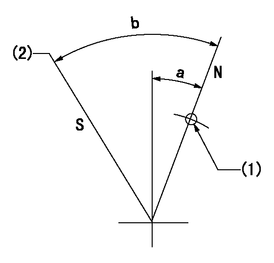
Speed control lever angle

F:Full speed
I:Idle
(1)Use the hole at R = aa
(2)Stopper bolt setting
----------
aa=34mm
----------
a=26deg+-5deg b=41deg+-3deg
----------
aa=34mm
----------
a=26deg+-5deg b=41deg+-3deg
Stop lever angle
N:Pump normal
S:Stop the pump.
(1)Use the pin at R = aa
(2)Set the stopper screw so that speed = bb and the rack position = cc (after setting apply red paint).
----------
aa=40mm bb=0r/min cc=1.5+-0.3mm
----------
a=20deg+-5deg b=44deg+-5deg
----------
aa=40mm bb=0r/min cc=1.5+-0.3mm
----------
a=20deg+-5deg b=44deg+-5deg
0000001501 RACK SENSOR

(VR) measurement voltage
(I) Part number of the control unit
(G) Apply red paint.
(H): End surface of the pump
1. Rack sensor adjustment (-0620)
(1)Fix the speed control lever at the full position
(2)Set the speed to N1 r/min.
(If the boost compensator is provided, apply boost pressure.)
(3)Adjust the bobbin (A) so that the rack sensor's output voltage is VR+-0.01.
(4)At that time, rack position must be Ra.
(5)Apply G at two places.
Connecting part between the joint (B) and the nut (F)
Connecting part between the joint (B) and the end surface of the pump (H)
----------
N1=650r/min Ra=R1(13)mm
----------
----------
N1=650r/min Ra=R1(13)mm
----------
Timing setting

(1)Pump vertical direction
(2)Coupling's key groove position at No 1 cylinder's beginning of injection
(3)-
(4)-
----------
----------
a=(30deg)
----------
----------
a=(30deg)
Information:
Electronic Controls
The electronic controller consists of two main components: the Electronic Control Module (ECM) and the Personality Module. The ECM is the computer which controls the PEEC engine. The Personality Module is the software which controls how the computer behaves. The two must be used together: neither can do anything by itself.Rack Controls
The rack mechanism on a PEEC III engine is very similar to a mechanical 3406 engine. The fuel injection pump is nearly identical; the rack is moved by a servo valve which receives oil pressure from the fuel injection pump. However, the PEEC III servo spool is moved by a solenoid (BTM) rather than by a linkage controlled by flyweights and springs.PEEC III determines a "desired rpm" based on the throttle position, vehicle speed, customer specified parameters, and certain diagnostic codes. The PEEC III governor tries to maintain the desired rpm by sensing actual engine speed using the engine speed sensor, then controlling the rack to achieve the desired rpm.PEEC III RPM Control Logic To move the rack, PEEC III adjusts the voltage to the rack solenoid (BTM) to increase rack. More voltage results in more rack. PEEC III knows how far the rack went by reading the rack position sensor. PEEC III increases the voltage to the rack solenoid until it senses the rack is in the desired position.PEEC III Electronic Governor PEEC III sets certain limits on rack motion. "FRC Rack" is a rack limit based on fuel-air ratio control, for emissions purposes. It works similar to a mechanical engine FARC; when PEEC III senses a higher boost pressure (more air into cylinder), it increases the FRC Rack limit, which allows more fuel into the cylinder. "Rated Rack" is a rack limit based on horsepower of the engine. It is similar to the rack stops and torque springs on a mechanical engine. It provides horsepower and torque curves for a specific engine family and rating. All of these limits are programmed by the factory into the personality module.Timing Advance Controls
The timing advance mechanism is the same as the 3406 mechanical engine, except the Timing solenoid (BTM), instead of the flyweights, controls timing advance. PEEC III adjusts voltage to the timing solenoid to change timing advance. More voltage results in more timing advance. PEEC III knows how much advance was achieved by reading the timing position sensor. PEEC III simply increases voltage to the timing solenoid until it senses that the timing advance is in the desired position.PEEC III Timing Advance Programmable Parameters
Certain parameters that affect PEEC III 3406 Diesel Engine operation may be changed with electronic service tools (either the ECAP or DDT). The parameters are stored in the ECM, and are protected from unauthorized changes by passwords.These parameters are either "System Configuration Parameters" or "Customer Parameters". System Configuration Parameters are those that effect horsepower family or emissions. Customer Parameters are those that affect cruise control, vehicle speed limits, progressive shifting, horsepower rating within a family, engine protection mode, and PTO operation.Some parameters may