Information injection-pump assembly
ZEXEL
106671-5360
1066715360
NISSAN-DIESEL
1679096568
1679096568
Rating:
Cross reference number
ZEXEL
106671-5360
1066715360
NISSAN-DIESEL
1679096568
1679096568
Zexel num
Bosch num
Firm num
Name
106671-5360
1679096568 NISSAN-DIESEL
INJECTION-PUMP ASSEMBLY
PF6TA * K
PF6TA * K
Calibration Data:
Adjustment conditions
Test oil
1404 Test oil ISO4113 or {SAEJ967d}
1404 Test oil ISO4113 or {SAEJ967d}
Test oil temperature
degC
40
40
45
Nozzle and nozzle holder
105780-8140
Bosch type code
EF8511/9A
Nozzle
105780-0000
Bosch type code
DN12SD12T
Nozzle holder
105780-2080
Bosch type code
EF8511/9
Opening pressure
MPa
17.2
Opening pressure
kgf/cm2
175
Injection pipe
Outer diameter - inner diameter - length (mm) mm 8-3-600
Outer diameter - inner diameter - length (mm) mm 8-3-600
Overflow valve
134424-0020
Overflow valve opening pressure
kPa
157
123
191
Overflow valve opening pressure
kgf/cm2
1.6
1.25
1.95
Tester oil delivery pressure
kPa
157
157
157
Tester oil delivery pressure
kgf/cm2
1.6
1.6
1.6
Direction of rotation (viewed from drive side)
Right R
Right R
Injection timing adjustment
Direction of rotation (viewed from drive side)
Right R
Right R
Injection order
1-4-2-6-
3-5
Pre-stroke
mm
3.9
3.85
3.95
Beginning of injection position
Drive side NO.1
Drive side NO.1
Difference between angles 1
Cal 1-4 deg. 60 59.5 60.5
Cal 1-4 deg. 60 59.5 60.5
Difference between angles 2
Cyl.1-2 deg. 120 119.5 120.5
Cyl.1-2 deg. 120 119.5 120.5
Difference between angles 3
Cal 1-6 deg. 180 179.5 180.5
Cal 1-6 deg. 180 179.5 180.5
Difference between angles 4
Cal 1-3 deg. 240 239.5 240.5
Cal 1-3 deg. 240 239.5 240.5
Difference between angles 5
Cal 1-5 deg. 300 299.5 300.5
Cal 1-5 deg. 300 299.5 300.5
Injection quantity adjustment
Adjusting point
A
Rack position
12.1
Pump speed
r/min
700
700
700
Average injection quantity
mm3/st.
194
192
196
Max. variation between cylinders
%
0
-4
4
Basic
*
Fixing the lever
*
Boost pressure
kPa
80
80
Boost pressure
mmHg
600
600
Injection quantity adjustment_02
Adjusting point
-
Rack position
6.3+-0.5
Pump speed
r/min
375
375
375
Average injection quantity
mm3/st.
14
13
15
Max. variation between cylinders
%
0
-10
10
Fixing the rack
*
Boost pressure
kPa
0
0
0
Boost pressure
mmHg
0
0
0
Remarks
Adjust only variation between cylinders; adjust governor according to governor specifications.
Adjust only variation between cylinders; adjust governor according to governor specifications.
Boost compensator adjustment
Pump speed
r/min
500
500
500
Rack position
9.2
Boost pressure
kPa
8
5.3
10.7
Boost pressure
mmHg
60
40
80
Boost compensator adjustment_02
Pump speed
r/min
500
500
500
Rack position
(12.1)
Boost pressure
kPa
66.7
60
73.4
Boost pressure
mmHg
500
450
550
Timer adjustment
Pump speed
r/min
750--
Advance angle
deg.
0
0
0
Remarks
Start
Start
Timer adjustment_02
Pump speed
r/min
700
Advance angle
deg.
0.5
Timer adjustment_03
Pump speed
r/min
1050
Advance angle
deg.
1
0.5
1.5
Remarks
Finish
Finish
Test data Ex:
Governor adjustment
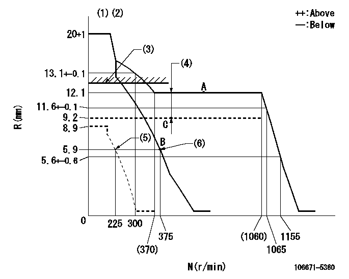
N:Pump speed
R:Rack position (mm)
(1)Target notch: K
(2)Tolerance for racks not indicated: +-0.05mm.
(3)Boost compensator excessive fuel lever at operation: L1 (at 0 boost pressure)
(4)Boost compensator stroke: BCL
(5)Set idle sub-spring
(6)Main spring setting
----------
K=11 L1=12.3+0.2mm BCL=(2.9)+-0.1mm
----------
----------
K=11 L1=12.3+0.2mm BCL=(2.9)+-0.1mm
----------
Speed control lever angle
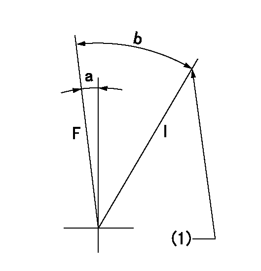
F:Full speed
I:Idle
(1)Stopper bolt setting
----------
----------
a=7deg+-5deg b=21deg+-5deg
----------
----------
a=7deg+-5deg b=21deg+-5deg
Stop lever angle

N:Pump normal
S:Stop the pump.
----------
----------
a=26deg+-5deg b=53deg+-5deg
----------
----------
a=26deg+-5deg b=53deg+-5deg
0000001101

N:Normal
B:When boosted
(1)Rack position = aa at boost pressure 0.
----------
aa=12.3+0.2mm
----------
a=(17deg) b=(18deg)
----------
aa=12.3+0.2mm
----------
a=(17deg) b=(18deg)
Timing setting

(1)Pump vertical direction
(2)Coupling's key groove position at No 1 cylinder's beginning of injection
(3)-
(4)-
----------
----------
a=(30deg)
----------
----------
a=(30deg)
Information:
1. Disconnect plug P7 from receptacle J7. Check the connections for damaged wires or pins and corrosion. Also check that the pins are at the proper height in the connector. Check that the wires and pins are tight in the connectors by pulling (slightly) on each wire of each connector (including the breakout "T").2. Install the 9X1160 Adapter (forty pin breakout "T") between J7 and P7 and secure the connections.3. Connect the voltmeter as shown. Check for the appropriate voltages between the lettered "T" pins as explained in Steps 4 through 18.4. Check system voltage.Pin 1 (+) to pin 2 (ground) system voltage should be approximately 12 volts DC with key on (no accessories). Minimum voltage is 11.0 volts DC. While cranking the voltage should be 8 to 12 volts DC. Diagnosis - Using the truck wiring schematic, check wires 1 and 2 and connections from J7 through the truck wiring harness back to the battery terminals for proper voltage.5. Check voltage drop from battery.If the voltage check between pins 1 and 2 on P7 is less than 11.0 volts with the key on, check the voltage drop from pin 2 of the J7 connector to the negative battery post while cranking. For this test, the common lead (black) should be connected to the negative battery post first. Then place the positive (red) lead into pin 2. (Pin 2 is chassis ground). Voltage should be less than .5 volts DC when cranking. Diagnosis - If voltage drop is greater than .5 volts DC, check wire 2 and connections (including the battery post connections) from J7 to battery negative.6. Parking BrakePin 11 (parking brake) to 2 (ground):* Less than .5 volts DC with the key on and parking brake applied.* More than 4.5 volts DC with the key on and parking brake released. Diagnosis - Disconnect breakout "T" and check the individual switch circuits for open, ground or faulty switch. Switch circuit must have less than 10 ohms resistance and more than 20,000 ohms resistance to chassis ground.7. Check brake switch.Pin 30 (brake switch) to 2:* Less than .5 volts DC with the key on.* More than 4.5 volts DC with brake pedal applied and the key on. Diagnosis - Disconnect breakout "T" and check the individual switch circuits for open, ground or faulty switch. Switch circuit must have less than 2.5 ohms resistance and more than 5000 ohms resistance to chassis ground.8. Check vehicle speed buffer.When testing for speedometer problems on trucks that have a single sensor with a single winding for vehicle speed, also follow J14 tests 6, 7 and 8.A. Disconnect the two buffer input wires from the Vehicle Speed Sensor. Using a long jumper wire, connect the white input wire to P7 Pin 1 (+ battery).* With key ON, engine OFF, measure voltage from P7 Pin 33 (vehicle speed) and P7
Have questions with 106671-5360?
Group cross 106671-5360 ZEXEL
Nissan-Diesel
Nissan-Diesel
Nissan-Diesel
Nissan-Diesel
106671-5360
1679096568
INJECTION-PUMP ASSEMBLY
PF6TA
PF6TA