Information injection-pump assembly
ZEXEL
106671-5341
1066715341
NISSAN-DIESEL
1680095501
1680095501
Rating:
Cross reference number
ZEXEL
106671-5341
1066715341
NISSAN-DIESEL
1680095501
1680095501
Zexel num
Bosch num
Firm num
Name
Calibration Data:
Adjustment conditions
Test oil
1404 Test oil ISO4113 or {SAEJ967d}
1404 Test oil ISO4113 or {SAEJ967d}
Test oil temperature
degC
40
40
45
Nozzle and nozzle holder
105780-8140
Bosch type code
EF8511/9A
Nozzle
105780-0000
Bosch type code
DN12SD12T
Nozzle holder
105780-2080
Bosch type code
EF8511/9
Opening pressure
MPa
17.2
Opening pressure
kgf/cm2
175
Injection pipe
Outer diameter - inner diameter - length (mm) mm 8-3-600
Outer diameter - inner diameter - length (mm) mm 8-3-600
Overflow valve
134424-4120
Overflow valve opening pressure
kPa
255
221
289
Overflow valve opening pressure
kgf/cm2
2.6
2.25
2.95
Tester oil delivery pressure
kPa
157
157
157
Tester oil delivery pressure
kgf/cm2
1.6
1.6
1.6
Direction of rotation (viewed from drive side)
Right R
Right R
Injection timing adjustment
Direction of rotation (viewed from drive side)
Right R
Right R
Injection order
1-4-2-6-
3-5
Pre-stroke
mm
4.4
4.37
4.43
Beginning of injection position
Drive side NO.1
Drive side NO.1
Difference between angles 1
Cal 1-4 deg. 60 59.5 60.5
Cal 1-4 deg. 60 59.5 60.5
Difference between angles 2
Cyl.1-2 deg. 120 119.5 120.5
Cyl.1-2 deg. 120 119.5 120.5
Difference between angles 3
Cal 1-6 deg. 180 179.5 180.5
Cal 1-6 deg. 180 179.5 180.5
Difference between angles 4
Cal 1-3 deg. 240 239.5 240.5
Cal 1-3 deg. 240 239.5 240.5
Difference between angles 5
Cal 1-5 deg. 300 299.5 300.5
Cal 1-5 deg. 300 299.5 300.5
Injection quantity adjustment
Adjusting point
-
Rack position
12.8
Pump speed
r/min
650
650
650
Average injection quantity
mm3/st.
144.5
141.5
147.5
Max. variation between cylinders
%
0
-4
4
Basic
*
Fixing the rack
*
Standard for adjustment of the maximum variation between cylinders
*
Injection quantity adjustment_02
Adjusting point
Z
Rack position
8+-0.5
Pump speed
r/min
530
530
530
Average injection quantity
mm3/st.
10
9
11
Max. variation between cylinders
%
0
-10
10
Fixing the rack
*
Standard for adjustment of the maximum variation between cylinders
*
Injection quantity adjustment_03
Adjusting point
A
Rack position
R1(12.8)
Pump speed
r/min
650
650
650
Average injection quantity
mm3/st.
144.5
142.5
146.5
Basic
*
Fixing the lever
*
Boost pressure
kPa
41.3
41.3
Boost pressure
mmHg
310
310
Injection quantity adjustment_04
Adjusting point
B
Rack position
R1+0.15
Pump speed
r/min
1250
1250
1250
Average injection quantity
mm3/st.
122.5
116.5
128.5
Fixing the lever
*
Boost pressure
kPa
41.3
41.3
Boost pressure
mmHg
310
310
Injection quantity adjustment_05
Adjusting point
C
Rack position
R2(R1-1.
05)
Pump speed
r/min
300
300
300
Average injection quantity
mm3/st.
116.5
110.5
122.5
Fixing the lever
*
Boost pressure
kPa
41.3
41.3
Boost pressure
mmHg
310
310
Injection quantity adjustment_06
Adjusting point
D
Rack position
R2-1.35
Pump speed
r/min
300
300
300
Average injection quantity
mm3/st.
58.5
52.5
64.5
Fixing the lever
*
Boost pressure
kPa
0
0
0
Boost pressure
mmHg
0
0
0
Boost compensator adjustment
Pump speed
r/min
300
300
300
Rack position
R2-1.35
Boost pressure
kPa
6.7
5.4
8
Boost pressure
mmHg
50
40
60
Boost compensator adjustment_02
Pump speed
r/min
300
300
300
Rack position
R2(R1-1.
05)
Boost pressure
kPa
28
28
28
Boost pressure
mmHg
210
210
210
Test data Ex:
Governor adjustment
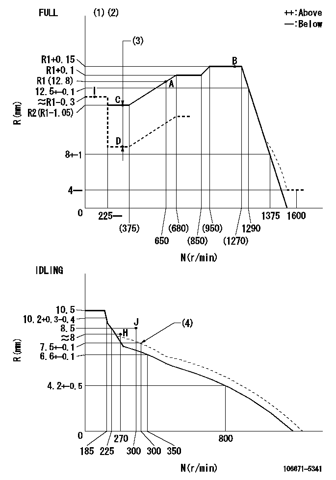
N:Pump speed
R:Rack position (mm)
(1)Torque cam stamping: T1
(2)Tolerance for racks not indicated: +-0.05mm.
(3)Boost compensator stroke: BCL
(4)Damper spring setting
----------
T1=AC32 BCL=1.35+-0.1mm
----------
----------
T1=AC32 BCL=1.35+-0.1mm
----------
Timer adjustment
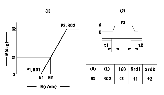
(1)Adjusting range
(2)Step response time
(N): Speed of the pump
(L): Load
(theta) Advance angle
(Srd1) Step response time 1
(Srd2) Step response time 2
1. Adjusting conditions for the variable timer
(1)Adjust the clearance between the pickup and the protrusion to L.
----------
L=1-0.2mm N3=800r/min C3=(7)deg t1=2--sec. t2=2--sec.
----------
N1=1000++r/min N2=1250r/min P1=0kPa(0kgf/cm2) P2=392kPa(4kgf/cm2) C1=4--deg C2=7+-0.3deg R01=0/4load R02=4/4load
----------
L=1-0.2mm N3=800r/min C3=(7)deg t1=2--sec. t2=2--sec.
----------
N1=1000++r/min N2=1250r/min P1=0kPa(0kgf/cm2) P2=392kPa(4kgf/cm2) C1=4--deg C2=7+-0.3deg R01=0/4load R02=4/4load
Speed control lever angle

F:Full speed
I:Idle
(1)Use the hole at R = aa
(2)Stopper bolt set position 'H'
----------
aa=39mm
----------
a=34deg+-5deg b=41deg+-3deg
----------
aa=39mm
----------
a=34deg+-5deg b=41deg+-3deg
Stop lever angle
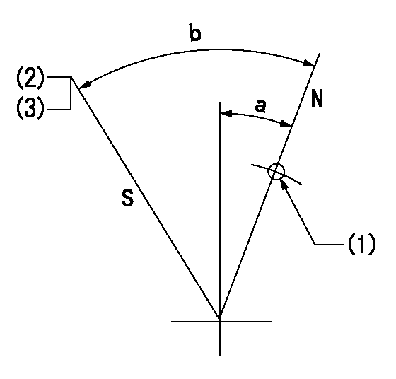
N:Pump normal
S:Stop the pump.
(1)Use the pin at R = aa
(2)Speed = bb, rack position = cc
(3)Set the stopper screw. (After setting, apply red paint.)
----------
aa=40mm bb=0r/min cc=1.5+-0.3mm
----------
a=20deg+-5deg b=44deg+-5deg
----------
aa=40mm bb=0r/min cc=1.5+-0.3mm
----------
a=20deg+-5deg b=44deg+-5deg
0000001501 RACK SENSOR

(VR) measurement voltage
(I) Part number of the control unit
(G) Apply red paint.
(H): End surface of the pump
1. Rack sensor adjustment (-0620)
(1)Fix the speed control lever at the full position
(2)Set the speed to N1 r/min.
(If the boost compensator is provided, apply boost pressure.)
(3)Adjust the bobbin (A) so that the rack sensor's output voltage is VR+-0.01.
(4)At that time, rack position must be Ra.
(5)Apply G at two places.
Connecting part between the joint (B) and the nut (F)
Connecting part between the joint (B) and the end surface of the pump (H)
----------
N1=650r/min Ra=R1(12.8)mm
----------
----------
N1=650r/min Ra=R1(12.8)mm
----------
Timing setting

(1)Pump vertical direction
(2)Coupling's key groove position at No 1 cylinder's beginning of injection
(3)-
(4)-
----------
----------
a=(30deg)
----------
----------
a=(30deg)
Information:
7. Remove inner fuel lines (13). 8. Remove Jacobs washers (14) and Jacobs shims (15) from the Jacobs stud assemblies. 9. Remove bolt (17) and two Jacobs stud assemblies (16) that hold the rocker shaft assembly to the head. Remove rocker shaft assembly (18). 10. Remove Jacobs exhaust valve bridges (20) from the exhaust valves only. The intake valves have the Caterpillar intake valve bridges. Remove the Caterpillar intake valve bridges (19).Install Jacobs Engine Brake
Do each step for each end of the engine. The front half is shown.1. Put clean engine oil on the bridges and dowels.2. Install Jacobs exhaust valve bridges (20) and the Caterpillar intake valve bridges (19) on the dowels.3. Keep hand pressure on the bridges, and turn the adjustment screw clockwise until contact is made with the valve stem. Turn the screw an extra 20° to 30°. This will make the dowel straight in the guide and compensate for gap (slack) in the threads. Hold the adjustment screw in this position, and tighten the locknut to a torque of 28 4 N m (21 3 lb.ft.). 4. Put rocker shaft assembly (18) in position on the cylinder head. 5. Install Jacobs washers (21) on the Jacobs stud assemblies (16). Put clean oil on the threads, and install washer and bolt (17) and Jacobs stud assemblies (16). Tighten the center bolt and Jacobs stud assemblies in increments of 70 N m (50 lb.ft.) each until a final torque of 450 N m (330 lb.ft.) is obtained.6. Make an adjustment to the valves to have a clearance of .015 (0.38 mm) for the intake valves and .030 (0.76 mm) for the exhaust valves. Tighten the locknuts to a torque of 28 4 N m (21 3 lb.ft.), and check the valve clearance again. See Testing And Adjusting for the correct procedure. 7. Install a new Jacobs O-ring seal (22) on the Jacobs oil supply adapter in the rocker shaft assembly. Put clean oil on the Jacobs O-ring seal.
Do not cause damage to the O-ring seals on the inner fuel lines.
8. Install inner fuel lines (13). Tighten the fuel line nuts to a torque of 40 7 N m (30 5 lb.ft.) with tooling (A) and (B). The Jacobs brake for the 3406B Truck Engine has only one support bracket (11).9. Put jacobs support brackets (11) in position as shown. Put oil on the threads of Jacobs bolts (12). Install the washers on the Jacobs bolts. Install Jacobs bolts (12) that hold the Jacobs support bracket in place. Tighten the Jacobs bolts to a torque of 450 N m (330 lb.ft.). 10. Install Jacobs washers (14) on the Jacobs stud assemblies.
Be extra careful not to cause damage to the Jacobs oil supply adapter O-ring seal when the Jacobs brake housing assembly is installed.
The brake housing assembly with the mark "FRONT" on it must be installed on the front three cylinders. The brake housing assembly with the mark "REAR" must be installed