Information injection-pump assembly
ZEXEL
106671-5220
1066715220

Rating:
Cross reference number
ZEXEL
106671-5220
1066715220
Zexel num
Bosch num
Firm num
Name
106671-5220
INJECTION-PUMP ASSEMBLY
Calibration Data:
Adjustment conditions
Test oil
1404 Test oil ISO4113 or {SAEJ967d}
1404 Test oil ISO4113 or {SAEJ967d}
Test oil temperature
degC
40
40
45
Nozzle and nozzle holder
105780-8140
Bosch type code
EF8511/9A
Nozzle
105780-0000
Bosch type code
DN12SD12T
Nozzle holder
105780-2080
Bosch type code
EF8511/9
Opening pressure
MPa
17.2
Opening pressure
kgf/cm2
175
Injection pipe
Outer diameter - inner diameter - length (mm) mm 8-3-600
Outer diameter - inner diameter - length (mm) mm 8-3-600
Overflow valve
132424-0620
Overflow valve opening pressure
kPa
157
123
191
Overflow valve opening pressure
kgf/cm2
1.6
1.25
1.95
Tester oil delivery pressure
kPa
157
157
157
Tester oil delivery pressure
kgf/cm2
1.6
1.6
1.6
Direction of rotation (viewed from drive side)
Right R
Right R
Injection timing adjustment
Direction of rotation (viewed from drive side)
Right R
Right R
Injection order
1-4-2-6-
3-5
Pre-stroke
mm
3.65
3.6
3.7
Beginning of injection position
Drive side NO.1
Drive side NO.1
Difference between angles 1
Cal 1-4 deg. 60 59.5 60.5
Cal 1-4 deg. 60 59.5 60.5
Difference between angles 2
Cyl.1-2 deg. 120 119.5 120.5
Cyl.1-2 deg. 120 119.5 120.5
Difference between angles 3
Cal 1-6 deg. 180 179.5 180.5
Cal 1-6 deg. 180 179.5 180.5
Difference between angles 4
Cal 1-3 deg. 240 239.5 240.5
Cal 1-3 deg. 240 239.5 240.5
Difference between angles 5
Cal 1-5 deg. 300 299.5 300.5
Cal 1-5 deg. 300 299.5 300.5
Injection quantity adjustment
Adjusting point
A
Rack position
11.6
Pump speed
r/min
600
600
600
Average injection quantity
mm3/st.
154.8
152.8
156.8
Max. variation between cylinders
%
0
-4
4
Basic
*
Fixing the lever
*
Boost pressure
kPa
29.3
29.3
Boost pressure
mmHg
220
220
Injection quantity adjustment_02
Adjusting point
C
Rack position
10.4
Pump speed
r/min
300
300
300
Average injection quantity
mm3/st.
117.4
115.4
119.4
Fixing the lever
*
Boost pressure
kPa
0
0
0
Boost pressure
mmHg
0
0
0
Injection quantity adjustment_03
Adjusting point
E
Rack position
7.8+-0.5
Pump speed
r/min
225
225
225
Average injection quantity
mm3/st.
14.3
13.3
15.3
Max. variation between cylinders
%
0
-10
10
Fixing the rack
*
Boost pressure
kPa
0
0
0
Boost pressure
mmHg
0
0
0
Boost compensator adjustment
Pump speed
r/min
300
300
300
Rack position
10.4
Boost pressure
kPa
4
2.7
5.3
Boost pressure
mmHg
30
20
40
Boost compensator adjustment_02
Pump speed
r/min
300
300
300
Rack position
12.3+0.2
Boost pressure
kPa
16
16
16
Boost pressure
mmHg
120
120
120
Timer adjustment
Pump speed
r/min
1200--
Advance angle
deg.
0
0
0
Remarks
Start
Start
Timer adjustment_02
Pump speed
r/min
1150
Advance angle
deg.
0.5
Timer adjustment_03
Pump speed
r/min
-
Advance angle
deg.
2
2
2
Remarks
Measure the actual speed, stop
Measure the actual speed, stop
Test data Ex:
Governor adjustment
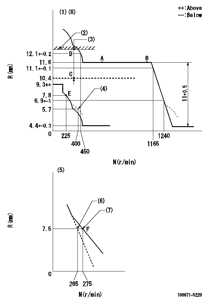
N:Pump speed
R:Rack position (mm)
(1)Tolerance for racks not indicated: +-0.05mm.
(2)Rack limit using the stop lever: R1
(3)Boost compensator stroke: BCL
(4)Damper spring setting
(5)Variable speed specification: idling adjustment
(6)Main spring setting
(7)Set idle sub-spring
(8)Perform governor adjustment at an ambient temperature of at least 15 deg C (boost compensator start spring is shape memory alloy).
----------
R1=12.3+0.2mm BCL=2+-0.1mm
----------
----------
R1=12.3+0.2mm BCL=2+-0.1mm
----------
Speed control lever angle
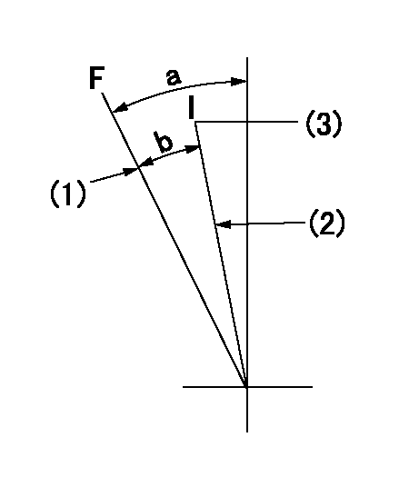
F:Full speed
I:Idle
(1)Stopper bolt setting
(2)Stopper bolt setting
(3)Set the pump speed at aa
----------
aa=275r/min
----------
a=23deg+-5deg b=15deg+-5deg
----------
aa=275r/min
----------
a=23deg+-5deg b=15deg+-5deg
0000000901
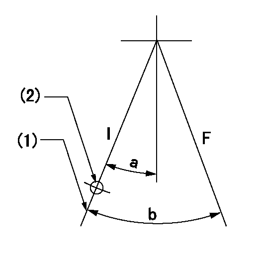
F:Full load
I:Idle
(1)Stopper bolt setting
(2)At center of threaded hole above R = aa
----------
aa=17mm
----------
a=15deg+-5deg b=27deg+-3deg
----------
aa=17mm
----------
a=15deg+-5deg b=27deg+-3deg
Stop lever angle
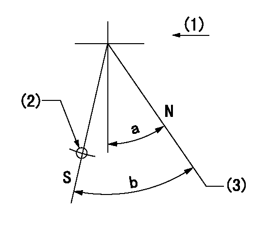
N:Pump normal
S:Stop the pump.
(1)Drive side
(2)Use the hole at R = aa
(3)Rack position bb
----------
aa=50mm bb=12.3+0.2mm
----------
a=30deg+-5deg b=32deg+-5deg
----------
aa=50mm bb=12.3+0.2mm
----------
a=30deg+-5deg b=32deg+-5deg
0000001501 ACS
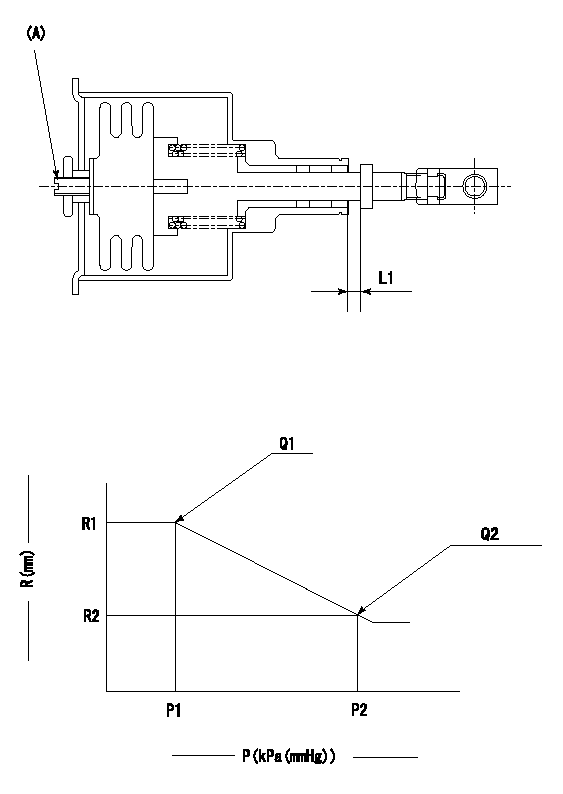
(A) Set screw
1. Aneroid compensator unit adjustment
Screw in (A) to obtain L1.
2. Adjustment following governor installation
(1)Set the speed of the pump to N1 r/min and fix the control lever at the full set position.
(2)Screw in the aneroid compensator to obtain the performance shown in the graph above.
----------
N1=1100r/min L1=0.1~0.5mm
----------
R1=11.6mm R2=(9.0)mm P1=90.6+-2.7kPa(680+-20mmHg) P2=57.7+-0.7kPa(433+-5mmHg) Q1=(152.6)+-4cm3/1000st Q2=90.2+-2cm3/1000st
----------
N1=1100r/min L1=0.1~0.5mm
----------
R1=11.6mm R2=(9.0)mm P1=90.6+-2.7kPa(680+-20mmHg) P2=57.7+-0.7kPa(433+-5mmHg) Q1=(152.6)+-4cm3/1000st Q2=90.2+-2cm3/1000st
Timing setting

(1)Pump vertical direction
(2)Coupling's key groove position at No 1 cylinder's beginning of injection
(3)-
(4)-
----------
----------
a=(30deg)
----------
----------
a=(30deg)
Information:
Typical Example1. With the rear of wire connector toward you, snap tool (A) (the correct size for the wire being removed) over the wire of the contact to be removed.2. Slide tool (A) along the wire into the contact cavity until it engages the contact and resistance is felt. Do not twist or insert tool (A) at an angle.
Typical Example3. Pull contact (2) and wire assembly out of connector (1).4. Remove the damaged contact from the wire.
Typical Example5. Use tool (B) and the following procedure to secure contact (2) to the wire.a. Strip 6.3 mm (.25 in.) insulation from the wire.b. Raise selector knob (3) and rotate until arrow is aligned with the wire size to be crimped.c. Loosen locknut. Turn adjusting screw (4) in (clockwise) until it stops.
Typical Exampled. Insert contact (2) into tool (B). Turn the adjusting screw out (counter clockwise) until the contact is flush with indentor cover (5) on tool (B). Tighten locknut.
Typical Examplec. Insert wire in contact (2). The contact must be centered between the indentors. Close the handles until the handle contacts the stop.d. Release the handles and remove the crimped contact.e. Inspect the contact to insure that all wire strands are inside the crimp barrel. Look in the hole in the contact. If the crimp is correct wire strands will be visable in the hole in the contact.
Typical Example6. Grasp the wire approximately 25.4 mm (1.00 in.) behind the contact crimp barrel.7. Hold connector (1) with the rear grommet facing you.8. Push contact (2) straight into connector (1) until a positive stop is felt.9. Gently pull on the wire and connector assembly to confirm that the contact is properly locked in place.
Have questions with 106671-5220?
Group cross 106671-5220 ZEXEL
Nissan-Diesel
Nissan-Diesel
106671-5220
INJECTION-PUMP ASSEMBLY