Information injection-pump assembly
BOSCH
F 019 Z10 530
f019z10530
ZEXEL
106671-5190
1066715190
Rating:
Service parts 106671-5190 INJECTION-PUMP ASSEMBLY:
1.
_
7.
COUPLING PLATE
8.
_
9.
_
11.
Nozzle and Holder
1660096571
12.
Open Pre:MPa(Kqf/cm2)
17.7(180)/22.6(230)

15.
NOZZLE SET
Include in #1:
106671-5190
as INJECTION-PUMP ASSEMBLY
Cross reference number
BOSCH
F 019 Z10 530
f019z10530
ZEXEL
106671-5190
1066715190
Zexel num
Bosch num
Firm num
Name
Calibration Data:
Adjustment conditions
Test oil
1404 Test oil ISO4113 or {SAEJ967d}
1404 Test oil ISO4113 or {SAEJ967d}
Test oil temperature
degC
40
40
45
Nozzle and nozzle holder
105780-8140
Bosch type code
EF8511/9A
Nozzle
105780-0000
Bosch type code
DN12SD12T
Nozzle holder
105780-2080
Bosch type code
EF8511/9
Opening pressure
MPa
17.2
Opening pressure
kgf/cm2
175
Injection pipe
Outer diameter - inner diameter - length (mm) mm 8-3-600
Outer diameter - inner diameter - length (mm) mm 8-3-600
Overflow valve
132424-0620
Overflow valve opening pressure
kPa
157
123
191
Overflow valve opening pressure
kgf/cm2
1.6
1.25
1.95
Tester oil delivery pressure
kPa
157
157
157
Tester oil delivery pressure
kgf/cm2
1.6
1.6
1.6
Direction of rotation (viewed from drive side)
Right R
Right R
Injection timing adjustment
Direction of rotation (viewed from drive side)
Right R
Right R
Injection order
1-4-2-6-
3-5
Pre-stroke
mm
3.9
3.85
3.95
Beginning of injection position
Drive side NO.1
Drive side NO.1
Difference between angles 1
Cal 1-4 deg. 60 59.5 60.5
Cal 1-4 deg. 60 59.5 60.5
Difference between angles 2
Cyl.1-2 deg. 120 119.5 120.5
Cyl.1-2 deg. 120 119.5 120.5
Difference between angles 3
Cal 1-6 deg. 180 179.5 180.5
Cal 1-6 deg. 180 179.5 180.5
Difference between angles 4
Cal 1-3 deg. 240 239.5 240.5
Cal 1-3 deg. 240 239.5 240.5
Difference between angles 5
Cal 1-5 deg. 300 299.5 300.5
Cal 1-5 deg. 300 299.5 300.5
Injection quantity adjustment
Adjusting point
A
Rack position
11.7
Pump speed
r/min
600
600
600
Average injection quantity
mm3/st.
188
186
190
Max. variation between cylinders
%
0
-4
4
Basic
*
Fixing the lever
*
Solenoid boost comp. OFF
*
Injection quantity adjustment_02
Adjusting point
C
Rack position
7+-0.5
Pump speed
r/min
225
225
225
Average injection quantity
mm3/st.
10
9
11
Max. variation between cylinders
%
0
-10
10
Fixing the rack
*
Solenoid boost comp. OFF
*
Injection quantity adjustment_03
Adjusting point
D
Rack position
9.35
Pump speed
r/min
300
300
300
Average injection quantity
mm3/st.
123.4
121.4
125.4
Fixing the lever
*
Solenoid boost comp. ON
*
Timer adjustment
Pump speed
r/min
900--
Advance angle
deg.
0
0
0
Load
3/4
Remarks
Start
Start
Timer adjustment_02
Pump speed
r/min
850
Advance angle
deg.
0.5
Load
3/4
Timer adjustment_03
Pump speed
r/min
1050
Advance angle
deg.
3
2.5
3.5
Load
4/4
Remarks
Finish
Finish
Test data Ex:
Governor adjustment
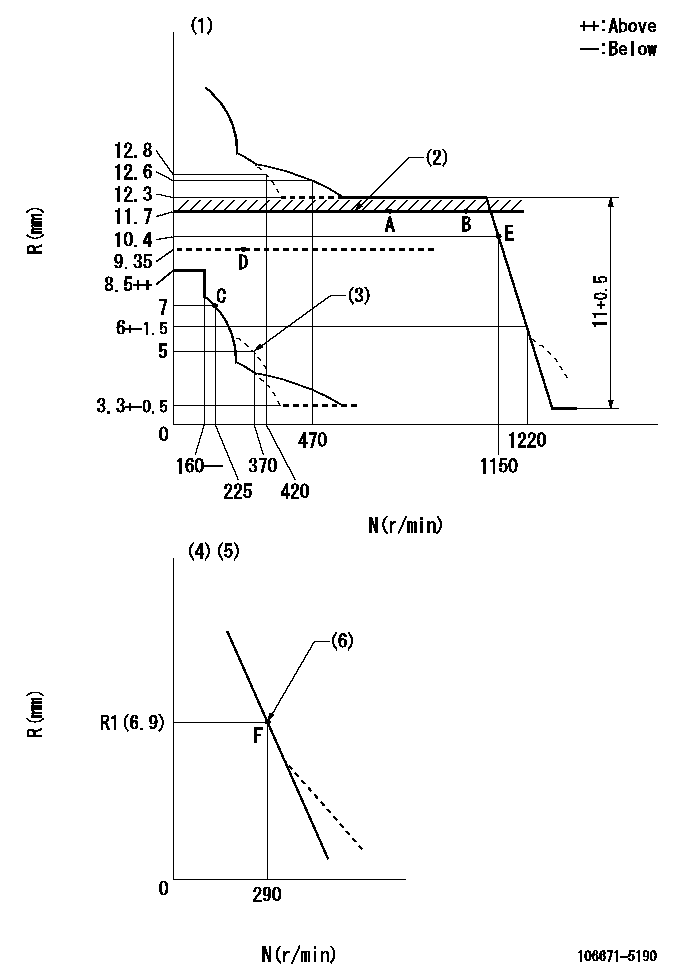
N:Pump speed
R:Rack position (mm)
(1)Tolerance for racks not indicated: +-0.05mm.
(2)Rack limit using stop lever
(3)Damper spring setting
(4)Variable speed specification: idling adjustment
(5)Fix the lever at the full-load position at delivery.
(6)Main spring setting
----------
----------
----------
----------
Speed control lever angle

F:Full speed
I:Idle
(1)Pump speed = aa
(2)Set the stopper bolt (fixed at full-load position at delivery.)
----------
aa=290r/min
----------
a=(13deg)+-5deg b=5.5deg+-5deg
----------
aa=290r/min
----------
a=(13deg)+-5deg b=5.5deg+-5deg
0000000901

F:Full load
I:Idle
(1)Stopper bolt setting
----------
----------
a=33.5deg+-3deg b=45deg+-5deg
----------
----------
a=33.5deg+-3deg b=45deg+-5deg
Stop lever angle
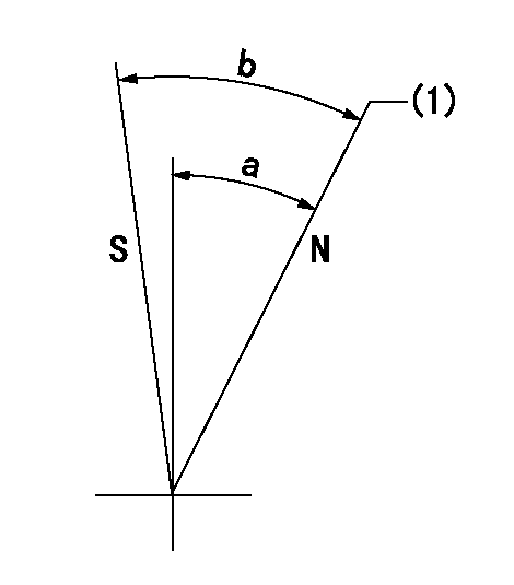
N:Pump normal
S:Stop the pump.
(1)Rack position = aa
----------
aa=11.7mm
----------
a=34.5deg+-5deg b=34.5deg+-5deg
----------
aa=11.7mm
----------
a=34.5deg+-5deg b=34.5deg+-5deg
0000001501 RACK SENSOR

(VR) measurement voltage
(I) Part number of the control unit
(G) Apply red paint.
(H): End surface of the pump
1. Rack sensor adjustment (-0620)
(1)Fix the speed control lever at the full position
(2)Set the speed to N1 r/min.
(If the boost compensator is provided, apply boost pressure.)
(3)Adjust the bobbin (A) so that the rack sensor's output voltage is VR+-0.01.
(4)At that time, rack position must be Ra.
(5)Apply G at two places.
Connecting part between the joint (B) and the nut (F)
Connecting part between the joint (B) and the end surface of the pump (H)
----------
N1=600r/min Ra=11.7mm
----------
----------
N1=600r/min Ra=11.7mm
----------
0000001601 BCS
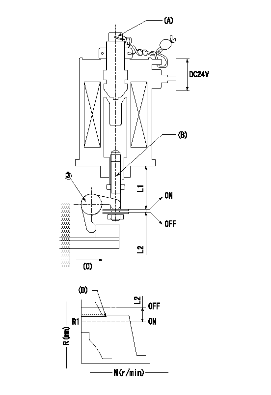
(A) Screw for precise adjustment
(B) Pre-adjustment screw
(C) Control rack, rack decrease direction
(D) Rack limit
1. Solenoid boost compensator adjustment
(1)Supply DC: V1 to the solenoid terminals and confirm solenoid operation.
(2)With the solenoid ON, calculate L1 from the value of R1. [L1 = La + (10.5 - R1) +-0.2]
(3)Adjust (B) to obtain L1.
(4)Assemble the solenoid to the governor.
(5)With the solenoid ON, readjust (B) so that R1 is within the allowance a.
(6)With the solenoid OFF, perform all governor adjustments except rack limit adjustment.
(7)Set the pump speed at N1 and turn the solenoid ON.
(8)Adjust (A) so that R1 is within the allowance range a.
(9)Set the pump speed at N1 and fix the load lever in the full position
(10)Turn the solenoid switch ON and OFF several times and confirm that the difference in rack positions is within L2.
(11)Set the rack limit.
(12)Stamp the solenoid valve.
----------
V1=24V N1=300r/min N2=0r/min R1=9.35mm a=+-0.5mm La=28mm L1=29.15+-0.2mm L2=3.5~5mm
----------
----------
V1=24V N1=300r/min N2=0r/min R1=9.35mm a=+-0.5mm La=28mm L1=29.15+-0.2mm L2=3.5~5mm
----------
Timing setting

(1)Pump vertical direction
(2)Coupling's key groove position at No 1 cylinder's beginning of injection
(3)-
(4)-
----------
----------
a=(30deg)
----------
----------
a=(30deg)
Information:
Actual RackThe ECM's interpretation of the signal from the Rack Position Sensor which represents actual position of the rack.Actual Timing AdvanceDegrees of advance beyond static, as measured by the Timing Position Sensor (assumes that Timing Position Sensor is calibrated).After Market DeviceA device or accessory installed by the customer after the vehicle is delivered.Air-To-Air Aftercooler (ATAAC)A means of cooling intake air after the turbocharger, using ambient air for cooling. The intake air is passed through an aftercooler (heat exchanger) mounted in front of the radiator before going to the intake manifold.Alternating Current (AC)The direction of current flow changes (alternates) regularly and constantly.American Wire Gauge (AWG)A measure of the diameter (and therefor the current carrying ability) of electrical wire. The smaller the AWG number, the larger the wire.Before Top Dead Center (BTDC) or Before Top Center (BTC)The 180° of crankshaft rotation before the piston reaches Top Dead Center (normal direction of rotation).Boost Pressure SensorThis sensor measures inlet manifold air pressure and sends a signal to the ECM.Brushless Torque Motor (BTM)Solenoid used to move fuel rack servo spool valve and timing advance spool valve.Bypass CircuitA circuit, usually temporary, to substitute for an existing circuit, typically for test purposes.CalibrationAs used here, is an electronic adjustment of a sensor signal.Cruise Control RangeThe range that the cruise control can operate within. Usually limited to the speed range anticipated on the open road.CodeSee Diagnostic Code.Customer Specified ParameterA Parameter that can be changed and whose value is set by the customer. Protected by Customer Passwords.Data LinkAn electrical connection for communication with other microprocessor based devices that are compatible with the American Trucking Association and SAE Standard such as trip recorders, electronic dashboards, and maintenance systems. The Data Link is also the communication medium used for programming and troubleshooting with Caterpillar devices.Desired Rack Position ("Des Rack Pos" on ECAP)The rack setting calculated by the ECM as needed to attain or maintain the Desired RPM.Desired RPMAn input to the electronic governor within the ECM. The electronic governor uses inputs from the Throttle Position Sensor, Engine Speed/Timing Sensor and Customer Parameters to determine "Desired RPM".Desired Timing Advance ("Des Timing Adv" on ECAP)The injection timing advance calculated by the ECM as required to meet emission and performance specifications.Diagnostic CodeSometimes referred to as a "fault code", it is an indication of a problem or event in the PEEC III System.Diagnostic LampSometimes referred to as the "check engine light", it is used to warn the operator of the presence of an active diagnostic code.Digital Diagnostic Tool (DDT)A Caterpillar electronic service tool used for programming and for diagnosing the 3406B PEEC III system.Direct CurrentThe type of current where the only direction of current flow is consistently in one direction only.Duty CycleSame as Pulse Width Modulation.Electronic Control Analyzer Programmer (ECAP)A Caterpillar Electronic Service Tool used for programming and diagnosing a variety of electronic controls. Electronic Control Module (ECM)The engine control computer that provides power to the PEEC III electronics, monitors PEEC III inputs and acts as a governor to control engine rpm.Engine Speed