Information injection-pump assembly
BOSCH
F 019 Z20 489
f019z20489
ZEXEL
106671-5121
1066715121
NISSAN-DIESEL
1679095503
1679095503
Rating:
Service parts 106671-5121 INJECTION-PUMP ASSEMBLY:
1.
_
7.
COUPLING PLATE
8.
_
9.
_
11.
Nozzle and Holder
16600-95501
12.
Open Pre:MPa(Kqf/cm2)
19.6{200}
15.
NOZZLE SET
Include in #1:
106671-5121
as INJECTION-PUMP ASSEMBLY
Cross reference number
BOSCH
F 019 Z20 489
f019z20489
ZEXEL
106671-5121
1066715121
NISSAN-DIESEL
1679095503
1679095503
Zexel num
Bosch num
Firm num
Name
106671-5121
F 019 Z20 489
1679095503 NISSAN-DIESEL
INJECTION-PUMP ASSEMBLY
NF6T04 * K 14CA PE6P,6PD PE
NF6T04 * K 14CA PE6P,6PD PE
Calibration Data:
Adjustment conditions
Test oil
1404 Test oil ISO4113 or {SAEJ967d}
1404 Test oil ISO4113 or {SAEJ967d}
Test oil temperature
degC
40
40
45
Nozzle and nozzle holder
105780-8140
Bosch type code
EF8511/9A
Nozzle
105780-0000
Bosch type code
DN12SD12T
Nozzle holder
105780-2080
Bosch type code
EF8511/9
Opening pressure
MPa
17.2
Opening pressure
kgf/cm2
175
Injection pipe
Outer diameter - inner diameter - length (mm) mm 8-3-600
Outer diameter - inner diameter - length (mm) mm 8-3-600
Overflow valve
131424-1420
Overflow valve opening pressure
kPa
157
123
191
Overflow valve opening pressure
kgf/cm2
1.6
1.25
1.95
Tester oil delivery pressure
kPa
157
157
157
Tester oil delivery pressure
kgf/cm2
1.6
1.6
1.6
Direction of rotation (viewed from drive side)
Right R
Right R
Injection timing adjustment
Direction of rotation (viewed from drive side)
Right R
Right R
Injection order
1-4-2-6-
3-5
Pre-stroke
mm
3.9
3.85
3.95
Beginning of injection position
Drive side NO.1
Drive side NO.1
Difference between angles 1
Cal 1-4 deg. 60 59.5 60.5
Cal 1-4 deg. 60 59.5 60.5
Difference between angles 2
Cyl.1-2 deg. 120 119.5 120.5
Cyl.1-2 deg. 120 119.5 120.5
Difference between angles 3
Cal 1-6 deg. 180 179.5 180.5
Cal 1-6 deg. 180 179.5 180.5
Difference between angles 4
Cal 1-3 deg. 240 239.5 240.5
Cal 1-3 deg. 240 239.5 240.5
Difference between angles 5
Cal 1-5 deg. 300 299.5 300.5
Cal 1-5 deg. 300 299.5 300.5
Injection quantity adjustment
Adjusting point
A
Rack position
8.4
Pump speed
r/min
700
700
700
Average injection quantity
mm3/st.
109.5
107.5
111.5
Max. variation between cylinders
%
0
-4
4
Basic
*
Fixing the lever
*
Boost pressure
kPa
36
36
Boost pressure
mmHg
270
270
Injection quantity adjustment_02
Adjusting point
B
Rack position
8.1+-0.5
Pump speed
r/min
1050
1050
1050
Average injection quantity
mm3/st.
97
93
101
Fixing the lever
*
Boost pressure
kPa
36
36
Boost pressure
mmHg
270
270
Injection quantity adjustment_03
Adjusting point
-
Rack position
7+-0.5
Pump speed
r/min
375
375
375
Average injection quantity
mm3/st.
26
25
27
Max. variation between cylinders
%
0
-10
10
Fixing the rack
*
Boost pressure
kPa
0
0
0
Boost pressure
mmHg
0
0
0
Remarks
Adjust only variation between cylinders; adjust governor according to governor specifications.
Adjust only variation between cylinders; adjust governor according to governor specifications.
Injection quantity adjustment_04
Adjusting point
D
Rack position
8.65
Pump speed
r/min
350
350
350
Average injection quantity
mm3/st.
101
95
107
Fixing the lever
*
Boost pressure
kPa
0
0
0
Boost pressure
mmHg
0
0
0
Boost compensator adjustment
Pump speed
r/min
350
350
350
Rack position
8.65
Boost pressure
kPa
18
15.3
20.7
Boost pressure
mmHg
135
115
155
Boost compensator adjustment_02
Pump speed
r/min
350
350
350
Rack position
8.9
Boost pressure
kPa
25.3
21.3
29.3
Boost pressure
mmHg
190
160
220
Boost compensator adjustment_03
Pump speed
r/min
350
350
350
Rack position
(9.1)
Remarks
Measure actual boost pressure.
Measure actual boost pressure.
Timer adjustment
Pump speed
r/min
550--
Advance angle
deg.
0
0
0
Remarks
Start
Start
Timer adjustment_02
Pump speed
r/min
500
Advance angle
deg.
0.5
Timer adjustment_03
Pump speed
r/min
1000
Advance angle
deg.
1.5
1
2
Timer adjustment_04
Pump speed
r/min
-
Advance angle
deg.
1.8
1.8
1.8
Remarks
Measure the actual speed, stop
Measure the actual speed, stop
Test data Ex:
Governor adjustment
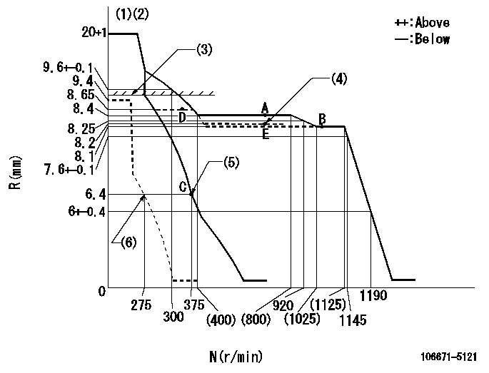
N:Pump speed
R:Rack position (mm)
(1)Target notch: K
(2)Tolerance for racks not indicated: +-0.05mm.
(3)Boost compensator excessive fuel lever at operation: L1 (at 0 boost pressure)
(4)Set the injection quantity changeover lever.
(5)Main spring setting
(6)Set idle sub-spring
----------
K=18 L1=9.8+-0.1mm
----------
----------
K=18 L1=9.8+-0.1mm
----------
Speed control lever angle

F:Full speed
I:Idle
(1)Stopper bolt setting
----------
----------
a=12deg+-5deg b=16deg+-5deg
----------
----------
a=12deg+-5deg b=16deg+-5deg
Stop lever angle
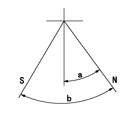
N:Pump normal
S:Stop the pump.
----------
----------
a=26deg+-5deg b=53deg+-5deg
----------
----------
a=26deg+-5deg b=53deg+-5deg
0000001101
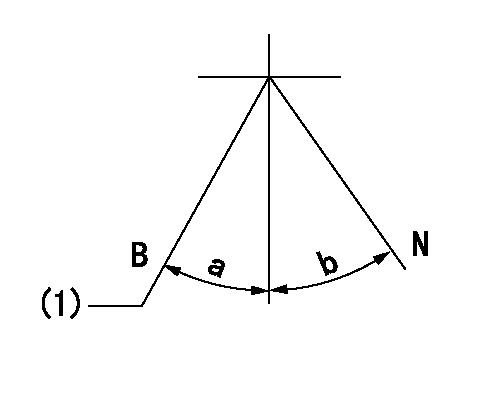
N:Normal
B:When boosted
(1)Rack position = aa at boost pressure 0.
----------
aa=9.8+-0.1mm
----------
a=(11deg) b=(18deg)
----------
aa=9.8+-0.1mm
----------
a=(11deg) b=(18deg)
0000001201
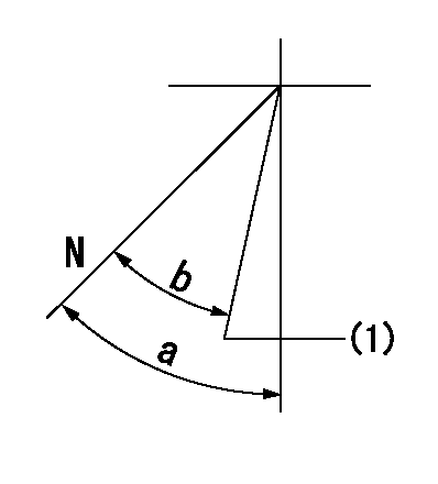
N:Normal
(1)Rack position = aa (point E setting)
----------
aa=8.2mm
----------
a=44deg+-5deg b=(40deg)+-5deg
----------
aa=8.2mm
----------
a=44deg+-5deg b=(40deg)+-5deg
Timing setting

(1)Pump vertical direction
(2)Coupling's key groove position at No 1 cylinder's beginning of injection
(3)B.T.D.C.: aa
(4)-
----------
aa=17deg
----------
a=(40deg)
----------
aa=17deg
----------
a=(40deg)
Information:
Programmable Parameters
Certain parameters that affect 3176 Diesel Truck Engine operation may be changed with electronic service tools (either the ECAP or DDT). The parameters are stored in the ECM, and are protected from unauthorized changes by passwords.These parameters are either "System Configuration Parameters" or "Customer Parameters". System Configuration Parameters are set at the factory and effect emissions or horsepower ratings within a family of engines. Factory passwords must be obtained and used to change System Configuration Parameters. Customer Parameters are variable and can be used to affect cruise control, vehicle speed limits, progressive shifting, rpm/horsepower ratings within the limits set by the factory, Caterpillar Engine Protection, and PTO operation. Customer Passwords are necessary to change Customer Specified Parameters.Some parameters may affect engine operation in ways a driver does not expect without adequate training. These may lead to power or performance complaints, even when the engine is performing to specifications.For example, the Vehicle Speed Limit (VSL) parameter is programmable, to allow the customer to electronically limit vehicle speed. When the programmed limit is reached, the ECM reduces the amount of fuel injected into the cylinders. Engine power is controlled and the VSL will not be exceeded. Also, Progressive Shift Parameters (such as Low Gear limits and High Gear limits) will cause the ECM to pause at a programmed engine rpm. This pause can be helpful to encourage more fuel efficient driving practices but may be misunderstood by the driver and result in a performance complaint.Passwords
"System Configuration Parameters" are protected by factory passwords. Factory passwords are calculated on a computer system available only to Caterpillar dealers. Since factory passwords contain alphabetic characters, only the ECAP may change System Configuration Parameters. System Configuration Parameters affect horsepower family or emissions."Customer Parameters" are protected by customer passwords. The customer passwords are programmed by the customer. Either the ECAP or DDT may change customer Parameters (although if a customer programs his password with alphabetic characters using an ECAP, only an ECAP can change Customer Parameters, since the DDT does not have alphabetic characters). See section 2.0 on "Programming 3176 Parameters", for more details when passwords are needed and how to obtain them.Self-Diagnostics
The 3176 electronics have some ability to diagnose themselves. When a problem is detected, a diagnostic code is generated and the diagnostic lamp is turned on. In most cases, the code is also stored in permanent memory in the ECM.Codes that represent current faults are called ACTIVE. They indicate that a problem of some kind currently exists. They should always be serviced first. See the section on "Troubleshooting Diagnostic Codes" in this manual for more details.Codes stored in memory are called LOGGED. Since the problem may have been temporary or may have been repaired since the time it was logged, logged codes don't necessarily mean something needs to be repaired. They are instead meant to be an indicator of probable causes for intermittent problems. In addition, some logged codes record "events", rather than failures. Codes not requiring passwords to clear are automatically deleted
Have questions with 106671-5121?
Group cross 106671-5121 ZEXEL
Nissan-Diesel
Nissan-Diesel
Nissan-Diesel
106671-5121
F 019 Z20 489
1679095503
INJECTION-PUMP ASSEMBLY
NF6T04
NF6T04