Information injection-pump assembly
ZEXEL
106671-4950
1066714950
MITSUBISHI-HEAV
3626503290
3626503290
Rating:
Service parts 106671-4950 INJECTION-PUMP ASSEMBLY:
1.
_
7.
COUPLING PLATE
8.
_
9.
_
11.
Nozzle and Holder
36261-11070
12.
Open Pre:MPa(Kqf/cm2)
21.6{220}
15.
NOZZLE SET
Include in #1:
106671-4950
as INJECTION-PUMP ASSEMBLY
Cross reference number
ZEXEL
106671-4950
1066714950
MITSUBISHI-HEAV
3626503290
3626503290
Zexel num
Bosch num
Firm num
Name
Calibration Data:
Adjustment conditions
Test oil
1404 Test oil ISO4113 or {SAEJ967d}
1404 Test oil ISO4113 or {SAEJ967d}
Test oil temperature
degC
40
40
45
Nozzle and nozzle holder
105780-8140
Bosch type code
EF8511/9A
Nozzle
105780-0000
Bosch type code
DN12SD12T
Nozzle holder
105780-2080
Bosch type code
EF8511/9
Opening pressure
MPa
17.2
Opening pressure
kgf/cm2
175
Injection pipe
Outer diameter - inner diameter - length (mm) mm 8-3-600
Outer diameter - inner diameter - length (mm) mm 8-3-600
Overflow valve
131424-1520
Overflow valve opening pressure
kPa
157
123
191
Overflow valve opening pressure
kgf/cm2
1.6
1.25
1.95
Tester oil delivery pressure
kPa
157
157
157
Tester oil delivery pressure
kgf/cm2
1.6
1.6
1.6
Direction of rotation (viewed from drive side)
Right R
Right R
Injection timing adjustment
Direction of rotation (viewed from drive side)
Right R
Right R
Injection order
1-5-3-6-
2-4
Pre-stroke
mm
3.9
3.85
3.95
Beginning of injection position
Governor side NO.1
Governor side NO.1
Difference between angles 1
Cal 1-5 deg. 60 59.5 60.5
Cal 1-5 deg. 60 59.5 60.5
Difference between angles 2
Cal 1-3 deg. 120 119.5 120.5
Cal 1-3 deg. 120 119.5 120.5
Difference between angles 3
Cal 1-6 deg. 180 179.5 180.5
Cal 1-6 deg. 180 179.5 180.5
Difference between angles 4
Cyl.1-2 deg. 240 239.5 240.5
Cyl.1-2 deg. 240 239.5 240.5
Difference between angles 5
Cal 1-4 deg. 300 299.5 300.5
Cal 1-4 deg. 300 299.5 300.5
Injection quantity adjustment
Adjusting point
A
Rack position
14.8
Pump speed
r/min
1000
1000
1000
Average injection quantity
mm3/st.
197
190
204
Max. variation between cylinders
%
0
-3
3
Basic
*
Fixing the lever
*
Boost pressure
kPa
111
111
Boost pressure
mmHg
835
835
Injection quantity adjustment_02
Adjusting point
D
Rack position
7.3+-0.5
Pump speed
r/min
250
250
250
Average injection quantity
mm3/st.
28
25
31
Max. variation between cylinders
%
0
-10
10
Fixing the rack
*
Boost pressure
kPa
0
0
0
Boost pressure
mmHg
0
0
0
Boost compensator adjustment
Pump speed
r/min
500
500
500
Rack position
(15.1)
Boost pressure
kPa
53.3
50.6
56
Boost pressure
mmHg
400
380
420
Boost compensator adjustment_02
Pump speed
r/min
500
500
500
Rack position
(15.6)
Boost pressure
kPa
98
91.3
104.7
Boost pressure
mmHg
735
685
785
Timer adjustment
Pump speed
r/min
470--
Advance angle
deg.
0
0
0
Remarks
Start
Start
Timer adjustment_02
Pump speed
r/min
420
Advance angle
deg.
0.5
Timer adjustment_03
Pump speed
r/min
720
Advance angle
deg.
4
3.5
4.5
Remarks
Finish
Finish
Test data Ex:
Governor adjustment
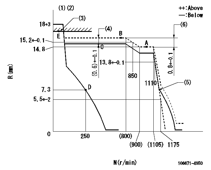
N:Pump speed
R:Rack position (mm)
(1)Notch fixed: K
(2)Tolerance for racks not indicated: +-0.05mm.
(3)RACK LIMIT: RAL
(4)Boost compensator stroke
(5)Idle sub spring setting: L1.
(6)Rack difference between N = N1 and N = N2
----------
K=10 RAL=18.9+0.2mm L1=7.3-0.5mm N1=1000r/min N2=750r/min
----------
----------
K=10 RAL=18.9+0.2mm L1=7.3-0.5mm N1=1000r/min N2=750r/min
----------
Speed control lever angle

F:Full speed
I:Idle
(1)Stopper bolt setting
----------
----------
a=(20deg)+-5deg b=(33deg)+-5deg
----------
----------
a=(20deg)+-5deg b=(33deg)+-5deg
Stop lever angle
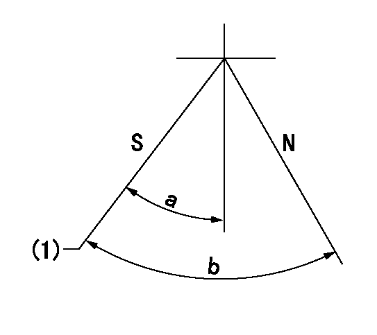
N:Pump normal
S:Stop the pump.
(1)Pump speed aa and rack position bb (to be sealed at delivery)
----------
aa=0r/min bb=1-0.2mm
----------
a=35deg+-5deg b=70deg+-5deg
----------
aa=0r/min bb=1-0.2mm
----------
a=35deg+-5deg b=70deg+-5deg
Timing setting

(1)Pump vertical direction
(2)Coupling's key groove position at No 1 cylinder's beginning of injection
(3)-
(4)-
----------
----------
a=(100deg)
----------
----------
a=(100deg)
Information:
1. Remove oil supply tube (1) from the turbocharger and the oil filter base.2. Remove four bolts (3), and remove oil drain tube (2) and elbow (4) from the turbocharger. Separate the elbow from the drain tube. Remove the O-ring seal from the tube. 3. Remove four nuts and bolts (6). Remove bolt (5) and remove tube (7).4. Remove the O-ring seal from tube (7). 5. Remove bolts (9), elbow (8) and pipe (10). 6. The weight of the turbocharger is approximately 24 kg (53 lb.). Fasten a nylon strap and a hoist to the turbocharger, and remove four bolts (12) and nuts that hold it to the exhaust manifold. Remove turbocharger (11). The following steps are for the installation of the turbocharger.7. Inspect all gaskets and O-ring seals for damage, and make a replacement if needed.8. Install a gasket between the turbocharger and exhaust manifold. Put 5P3931 Anti-Seize Compound on the threads of bolts (12). Put turbocharger (11) in position and install bolts and nuts (12). Tighten the bolts to a torque of 55 5 N m (41 4 lb. ft.).9. Apply 5P3931 Anti-Seize Compound to the male ends of pipe (10) and bolts (9). Install pipe (10) and elbow (8). Tighten bolts (9) to a torque of 55 5 N m (41 4 lb. ft.).10. Lubricate the O-ring seals with clean oil and install tube (7). Install bolts (5) and (6).11. Install the O-ring seal on tube (2). Lubricate the O-ring seal with clean oil and install tube (2) in elbow (4). Put the gaskets in position on the block and on the turbocharger, and install tube (2) with bolts (3).12. Put a gasket in position between oil supply tube (1) and the turbocharger. Install oil supply tube (1).Disassemble Turbocharger (Schwitzer 4MF)
Start By:a. remove turbocharger1. Put identification marks on the two housings and the cartridge assembly for use at assembly. 2. Remove two clamps (3) and make a separation of compressor housing (1) and turbine housing (2) from the cartridge assembly.
When the nut is loosened, do not put a side force on the shaft.
3. Put cartridge assembly (4) in position on tooling (A). Remove the nut from the shaft. 4. Use a press to push the shaft assembly out of the cartridge assembly. Remove compressor wheel (5). 5. Remove seal ring (8) and shroud (7) from shaft assembly (6). 6. Remove snap ring (9) with tool (B). 7. Use two screwdrivers to remove insert (10) from the cartridge housing. 8. Remove O-ring seal (12) from the insert.9. Remove sleeve (11) from the insert. Remove the seal ring from the sleeve. 10. Remove deflector (13) from the housing. 11. Remove ring (14) from the cartridge housing. 12. Remove sleeve (15) and bearing (16) from the cartridge housing. 13. Remove ring (17). 14. Use tool (C) to remove snap ring (19), bearing (18) and snap ring (20) from the cartridge housing. 15. Turn the cartridge housing over. Use tool (C) to remove snap ring