Information injection-pump assembly
BOSCH
9 400 616 834
9400616834
ZEXEL
106671-4930
1066714930

Rating:
Service parts 106671-4930 INJECTION-PUMP ASSEMBLY:
1.
_
7.
COUPLING PLATE
8.
_
9.
_
11.
Nozzle and Holder
12.
Open Pre:MPa(Kqf/cm2)
21.6{220}
15.
NOZZLE SET
Include in #1:
106671-4930
as INJECTION-PUMP ASSEMBLY
Cross reference number
BOSCH
9 400 616 834
9400616834
ZEXEL
106671-4930
1066714930
Zexel num
Bosch num
Firm num
Name
106671-4930
9 400 616 834
HYUNDAI
INJECTION-PUMP ASSEMBLY
6D22T * K
6D22T * K
Calibration Data:
Adjustment conditions
Test oil
1404 Test oil ISO4113 or {SAEJ967d}
1404 Test oil ISO4113 or {SAEJ967d}
Test oil temperature
degC
40
40
45
Nozzle and nozzle holder
105780-8140
Bosch type code
EF8511/9A
Nozzle
105780-0000
Bosch type code
DN12SD12T
Nozzle holder
105780-2080
Bosch type code
EF8511/9
Opening pressure
MPa
17.2
Opening pressure
kgf/cm2
175
Injection pipe
Outer diameter - inner diameter - length (mm) mm 8-3-600
Outer diameter - inner diameter - length (mm) mm 8-3-600
Overflow valve
131424-4620
Overflow valve opening pressure
kPa
255
221
289
Overflow valve opening pressure
kgf/cm2
2.6
2.25
2.95
Tester oil delivery pressure
kPa
157
157
157
Tester oil delivery pressure
kgf/cm2
1.6
1.6
1.6
Direction of rotation (viewed from drive side)
Right R
Right R
Injection timing adjustment
Direction of rotation (viewed from drive side)
Right R
Right R
Injection order
1-5-3-6-
2-4
Pre-stroke
mm
4.8
4.75
4.85
Beginning of injection position
Governor side NO.1
Governor side NO.1
Difference between angles 1
Cal 1-5 deg. 60 59.5 60.5
Cal 1-5 deg. 60 59.5 60.5
Difference between angles 2
Cal 1-3 deg. 120 119.5 120.5
Cal 1-3 deg. 120 119.5 120.5
Difference between angles 3
Cal 1-6 deg. 180 179.5 180.5
Cal 1-6 deg. 180 179.5 180.5
Difference between angles 4
Cyl.1-2 deg. 240 239.5 240.5
Cyl.1-2 deg. 240 239.5 240.5
Difference between angles 5
Cal 1-4 deg. 300 299.5 300.5
Cal 1-4 deg. 300 299.5 300.5
Injection quantity adjustment
Adjusting point
A
Rack position
10
Pump speed
r/min
950
950
950
Average injection quantity
mm3/st.
104.6
101.6
107.6
Max. variation between cylinders
%
0
-3
3
Basic
*
Fixing the lever
*
Injection quantity adjustment_02
Adjusting point
C
Rack position
5.7+-0.5
Pump speed
r/min
285
285
285
Average injection quantity
mm3/st.
12.6
10
15.2
Max. variation between cylinders
%
0
-15
15
Fixing the rack
*
Injection quantity adjustment_03
Adjusting point
D
Rack position
-
Pump speed
r/min
100
100
100
Average injection quantity
mm3/st.
133
113
153
Fixing the lever
*
Rack limit
*
Timer adjustment
Pump speed
r/min
650--
Advance angle
deg.
0
0
0
Remarks
Start
Start
Timer adjustment_02
Pump speed
r/min
600
Advance angle
deg.
0.5
Timer adjustment_03
Pump speed
r/min
950
Advance angle
deg.
2
1.5
2.5
Remarks
Finish
Finish
Test data Ex:
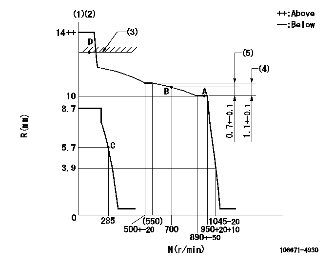
Governor adjustment

N:Pump speed
R:Rack position (mm)
(1)Target notch: K
(2)Supplied with torque spring not set.
(3)RACK LIMIT
(4)Rack difference between N = N1 and N = N2
(5)Rack difference to N = N3
----------
K=15 N1=950r/min N2=520r/min N3=950r/min
----------
----------
K=15 N1=950r/min N2=520r/min N3=950r/min
----------
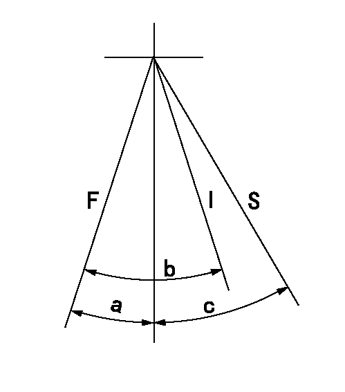
Speed control lever angle

F:Full speed
I:Idle
S:Stop
----------
----------
a=4deg+-5deg b=30deg+-5deg c=35deg+-3deg
----------
----------
a=4deg+-5deg b=30deg+-5deg c=35deg+-3deg
Stop lever angle

N:Pump normal
S:Stop the pump.
----------
----------
a=19deg+-5deg b=53deg+-5deg
----------
----------
a=19deg+-5deg b=53deg+-5deg
Timing setting

(1)Pump vertical direction
(2)Coupling's key groove position at No 1 cylinder's beginning of injection
(3)B.T.D.C.: aa
(4)-
----------
aa=16deg
----------
a=(7deg)
----------
aa=16deg
----------
a=(7deg)
Information:
1. Drain the coolant from the radiator. 2. Remove bolts (1) and grill (2). 3. Remove bolts (5) and fan guard (3). Remove bolts (6) and support bracket (4). Remove the enclosure group top panel (7).4. Remove the bolts holding the enclosure group side panels. Remove the side panels.5. Loosen the hose clamps on the upper and lower radiator hoses. Disconnect the radiator hoses from the radiator. 6. Use tooling (A) and attach a hoist to radiator (8). Remove the lower bolts holding the radiator to the base. Remove radiator (8). The weight of the radiator is 73 kg (161 lb.). The following steps are for the installation of the radiator.7. Use a hoist to install the radiator on the base. Install the bolts. Remove the hoist and tooling (A) from the radiator.8. Connect the upper and lower radiator hoses to the radiator. Tighten the hose clamps.9. Install the enclosure group side panels.10. Install the enclosure group top panel. Install the grill and the fan guard.11. Fill the radiator with coolant to the correct level. See the Maintenance Manual.Remove And Install Radiator And Radiator Guard (Prime)
1. Drain the coolant from the radiator. 2. Loosen hose clamps (4) and (5). Disconnect tube (1) from hose (6). Rotate tube (1) 180° for clearance. Remove bolts (2) from support arms (3). 3. Remove eight bolts (7) holding fan guard (8) to the radiator guard. 4. Install tool (A) and a hoist to the radiator. 5. Remove four bolts (10) that fasten the lower radiator elbow to the radiator. Separate the elbow from the radiator. Remove bolt (11) from the crankcase vent hose clamp.Remove four mounting bolts (9). Remove the radiator and radiator guard. The weight of the radiator and radiator guard is 250 Kg (550 lb.). The following steps are for the installation of the radiator and radiator guard.6. Use a hoist to put the radiator and radiator guard in position on the base. Install four mounting bolts (9). Remove the hoist and tool (A).7. Install the gasket and lower radiator elbow (12) to the radiator. Install bolts (10). Install bolt (11) and the clamp to hold the crankcase vent hose in place.8. Install bolts (7) to hold fan guard (8) in position.9. Connect tube (1) to hose (6) and tighten hose clamps (4) and (5). Install bolts (2) to secure control arms (3) to the radiator guard.10. Fill the radiator with coolant to the correct level. See the Maintenance Manual.Disassemble And Assemble Radiator
Start By:a. remove radiator and radiator guard **The radiator can be disassembled and assembled without removing the radiator and guard. 1. Remove eighteen bolts (2) and remove four plates (4). Remove four bolts, block off plate (1) and the gasket. Remove four bolts, upper radiator hose adapter (3) and the gasket. 2. Loosen four bolts (7). Disconnect tube assemblies (5) and (8). Remove four bolts (9) and remove coolant level switch if applicable. 3. Remove eleven bolts (11) and remove overflow tube (10), crankcase vent tube clamp (13)
Have questions with 106671-4930?
Group cross 106671-4930 ZEXEL
Niigata-Urawa
Hyundai
106671-4930
9 400 616 834
INJECTION-PUMP ASSEMBLY
6D22T
6D22T
