Information injection-pump assembly
ZEXEL
106671-4770
1066714770

Rating:
Service parts 106671-4770 INJECTION-PUMP ASSEMBLY:
1.
_
7.
COUPLING PLATE
8.
_
9.
_
11.
Nozzle and Holder
36261-33010
12.
Open Pre:MPa(Kqf/cm2)
21.6{220}
15.
NOZZLE SET
Include in #1:
106671-4770
as INJECTION-PUMP ASSEMBLY
Cross reference number
ZEXEL
106671-4770
1066714770
Zexel num
Bosch num
Firm num
Name
106671-4770
INJECTION-PUMP ASSEMBLY
Calibration Data:
Adjustment conditions
Test oil
1404 Test oil ISO4113 or {SAEJ967d}
1404 Test oil ISO4113 or {SAEJ967d}
Test oil temperature
degC
40
40
45
Nozzle and nozzle holder
105780-8140
Bosch type code
EF8511/9A
Nozzle
105780-0000
Bosch type code
DN12SD12T
Nozzle holder
105780-2080
Bosch type code
EF8511/9
Opening pressure
MPa
17.2
Opening pressure
kgf/cm2
175
Injection pipe
Outer diameter - inner diameter - length (mm) mm 8-3-600
Outer diameter - inner diameter - length (mm) mm 8-3-600
Overflow valve
131424-7420
Overflow valve opening pressure
kPa
255
221
289
Overflow valve opening pressure
kgf/cm2
2.6
2.25
2.95
Tester oil delivery pressure
kPa
157
157
157
Tester oil delivery pressure
kgf/cm2
1.6
1.6
1.6
Direction of rotation (viewed from drive side)
Right R
Right R
Injection timing adjustment
Direction of rotation (viewed from drive side)
Right R
Right R
Injection order
1-5-3-6-
2-4
Pre-stroke
mm
3.7
3.65
3.75
Beginning of injection position
Governor side NO.1
Governor side NO.1
Difference between angles 1
Cal 1-5 deg. 60 59.5 60.5
Cal 1-5 deg. 60 59.5 60.5
Difference between angles 2
Cal 1-3 deg. 120 119.5 120.5
Cal 1-3 deg. 120 119.5 120.5
Difference between angles 3
Cal 1-6 deg. 180 179.5 180.5
Cal 1-6 deg. 180 179.5 180.5
Difference between angles 4
Cyl.1-2 deg. 240 239.5 240.5
Cyl.1-2 deg. 240 239.5 240.5
Difference between angles 5
Cal 1-4 deg. 300 299.5 300.5
Cal 1-4 deg. 300 299.5 300.5
Injection quantity adjustment
Adjusting point
A
Rack position
10.7
Pump speed
r/min
750
750
750
Average injection quantity
mm3/st.
186
179
193
Max. variation between cylinders
%
0
-3
3
Basic
*
Fixing the rack
*
Injection quantity adjustment_02
Adjusting point
B
Rack position
3.8+-0.5
Pump speed
r/min
425
425
425
Average injection quantity
mm3/st.
8.5
6
11
Max. variation between cylinders
%
0
-10
10
Fixing the rack
*
Injection quantity adjustment_03
Adjusting point
C
Rack position
-
Pump speed
r/min
100
100
100
Average injection quantity
mm3/st.
233
233
243
Fixing the lever
*
Rack limit
*
Timer adjustment
Pump speed
r/min
(450)--
Advance angle
deg.
0
0
0
Remarks
Start
Start
Timer adjustment_02
Pump speed
r/min
400
Advance angle
deg.
0.5
Timer adjustment_03
Pump speed
r/min
500
Advance angle
deg.
0.9
Timer adjustment_04
Pump speed
r/min
700
Advance angle
deg.
1.2
0.7
1.7
Timer adjustment_05
Pump speed
r/min
-
Advance angle
deg.
4
3.5
4.5
Remarks
Measure the actual speed, stop
Measure the actual speed, stop
Test data Ex:
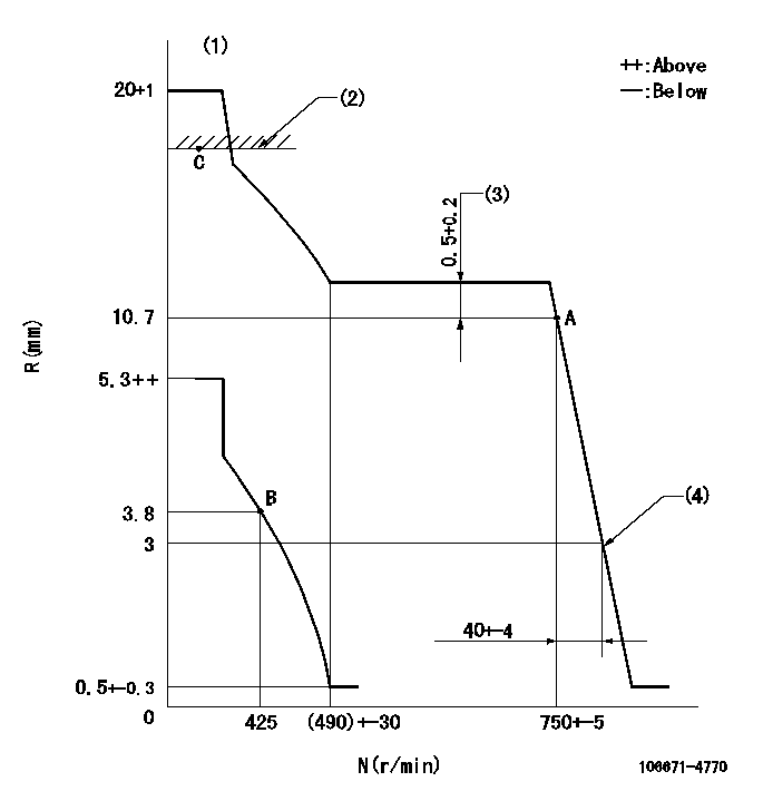
Governor adjustment

N:Pump speed
R:Rack position (mm)
(1)Target notch: K
(2)RACK LIMIT
(3)Rack difference between N = N1 and N = N2
(4)Idle sub spring setting: L1.
----------
K=18 N1=750r/min N2=700r/min L1=3-0.5mm
----------
----------
K=18 N1=750r/min N2=700r/min L1=3-0.5mm
----------
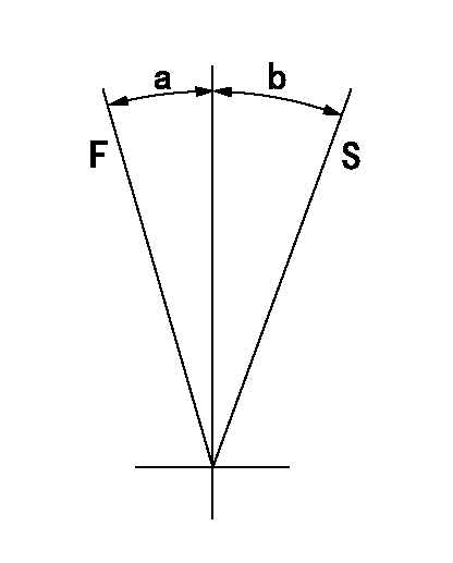
Speed control lever angle

F:Full speed
S:Stop
----------
----------
a=(8deg)+-5deg b=32deg+-3deg
----------
----------
a=(8deg)+-5deg b=32deg+-3deg
0000000901

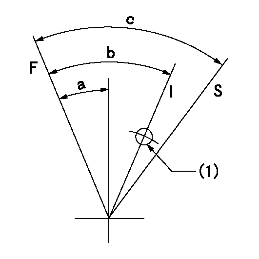
F:Full load
I:Idle
S:Stop
(1)Use the hole at R = aa
----------
aa=25mm
----------
a=26deg+-5deg b=28deg+-5deg c=53deg+-5deg
----------
aa=25mm
----------
a=26deg+-5deg b=28deg+-5deg c=53deg+-5deg
Timing setting

(1)Pump vertical direction
(2)Coupling's key groove position at No 1 cylinder's beginning of injection
(3)-
(4)-
----------
----------
a=(100deg)
----------
----------
a=(100deg)
Information:
13. Install spring (16), bellcrank (17). and retaining ring (15) on cover assembly (14). 14. Install gasket (24) bellcrank assembly (14) and two bolts (13) on timing advance housing. 15. Install timing advance housing (11) on the timing gear cover. Remove the screwdriver. 16. Check the position (protusion) of ball detent (25) in tool (B). It should protrude only slightly into the grooved area. During the following steps, tool (B) and the area of installation cannot be seen. The cutaway views are shown for better photo illustration. 17. Install tool (B) with grooved side toward the engine, between the power piston bearing and bellcrank (17) so that ear (26) is in an approximate 9 o'clock position. 18. Apply slight hand pressure and push tool (B) towards the engine and rotate counterclockwise slowly until ear (27) is in an approximate 9 o'clock position. A slight resistance as the tool starts to seat can be felt.19. Continue to rotate tool (B) counterclockwise until ear (27) is in an approximate 6 o'clock position. 20. Carefully install timing position sensor (6), spring (28), damping washer (29), bracket (8), collar (10) and locknut (9). Do not tighten locknut (9) at this time.21. Connect the wiring harness from the timing position sensor to the wiring harness on the engine. (P7/J7 connector). Be sure that the wiring harness from the PEEC control module is connected to the engine wiring harness. (P2/J2 connector).22. Disconnect the PEEC data link connector (the short pigtail out of the top of the PEEC control module - (P1/J1 connector) from the truck wiring harness and connect either tool (C) or tool (D) to the PEEC data link connector (J1 connector). Damping washer (29) must be installed above the flange om sensor (6). The aluminum surface of the damping washer (29) faces collar (10).23. Turn power on to the PEEC control module. Select "Timing Position Sensor Calibration" the main menu of tool (C) or (D). See special Instructions, Form No's. SEHS8742 and/or SEHS8743.
Do not engage the starter, or damage to the engine will be the result.
24. Adjust collar (10) on timing position sensor until the bar graph on tool (C) or (D) is centered and indicate the timing position sensor is calibrated.25. Tighten locknut (9) to 55 7 N*m (41 5 lb.ft.).26. Check the timing position calibration reading on tool (C) or (D) to insure that the timing position sensor is still in calibration after tightening the locknut.27. Turn off power to the PEEC control module.28. Disconnect tool (C) or (D) from the PEEC control module. Connect the PEEC data link connector (J1 connector) to the truck harness (P1 connector).29. Remove tool (B) from between the power piston and the bellcrank.30. Use tool (E) to rotate the engine in the clockwise direction to release the pressure on tool (F). Remove tool (F). 31. Lubricate O-ring seal (31) with engine oil and install on timing solenoid (5).32. Install timing solenoid (5) into the timing advance housing. Be sure lever (32) is
Have questions with 106671-4770?
Group cross 106671-4770 ZEXEL
Mitsubishi-Heav
Niigata-Urawa
Mitsubishi-Heav
Komatsu
Daewoo
106671-4770
INJECTION-PUMP ASSEMBLY