Information injection-pump assembly
ZEXEL
106671-4654
1066714654
NIIGATA-URAWA
75L47010F
75l47010f
Rating:
Service parts 106671-4654 INJECTION-PUMP ASSEMBLY:
1.
_
7.
COUPLING PLATE
8.
_
9.
_
10.
NOZZLE AND HOLDER ASSY
11.
Nozzle and Holder
12.
Open Pre:MPa(Kqf/cm2)
13.
NOZZLE-HOLDER
14.
NOZZLE
15.
NOZZLE SET
Include in #1:
106671-4654
as INJECTION-PUMP ASSEMBLY
Cross reference number
ZEXEL
106671-4654
1066714654
NIIGATA-URAWA
75L47010F
75l47010f
Zexel num
Bosch num
Firm num
Name
Calibration Data:
Adjustment conditions
Test oil
1404 Test oil ISO4113 or {SAEJ967d}
1404 Test oil ISO4113 or {SAEJ967d}
Test oil temperature
degC
40
40
45
Nozzle and nozzle holder
105780-8140
Bosch type code
EF8511/9A
Nozzle
105780-0000
Bosch type code
DN12SD12T
Nozzle holder
105780-2080
Bosch type code
EF8511/9
Opening pressure
MPa
17.2
Opening pressure
kgf/cm2
175
Injection pipe
Outer diameter - inner diameter - length (mm) mm 8-3-600
Outer diameter - inner diameter - length (mm) mm 8-3-600
Overflow valve
131425-0120
Overflow valve opening pressure
kPa
157
123
191
Overflow valve opening pressure
kgf/cm2
1.6
1.25
1.95
Tester oil delivery pressure
kPa
157
157
157
Tester oil delivery pressure
kgf/cm2
1.6
1.6
1.6
Direction of rotation (viewed from drive side)
Left L
Left L
Injection timing adjustment
Direction of rotation (viewed from drive side)
Left L
Left L
Injection order
1-4-2-6-
3-5
Pre-stroke
mm
3.05
3
3.1
Beginning of injection position
Governor side NO.1
Governor side NO.1
Difference between angles 1
Cal 1-4 deg. 60 59.5 60.5
Cal 1-4 deg. 60 59.5 60.5
Difference between angles 2
Cyl.1-2 deg. 120 119.5 120.5
Cyl.1-2 deg. 120 119.5 120.5
Difference between angles 3
Cal 1-6 deg. 180 179.5 180.5
Cal 1-6 deg. 180 179.5 180.5
Difference between angles 4
Cal 1-3 deg. 240 239.5 240.5
Cal 1-3 deg. 240 239.5 240.5
Difference between angles 5
Cal 1-5 deg. 300 299.5 300.5
Cal 1-5 deg. 300 299.5 300.5
Injection quantity adjustment
Adjusting point
A
Rack position
13.6
Pump speed
r/min
1000
1000
1000
Average injection quantity
mm3/st.
236
231
241
Max. variation between cylinders
%
0
-3
3
Basic
*
Fixing the lever
*
Injection quantity adjustment_02
Adjusting point
B
Rack position
5.5+-0.5
Pump speed
r/min
300
300
300
Average injection quantity
mm3/st.
17
15.5
18.5
Max. variation between cylinders
%
0
-10
10
Fixing the rack
*
Timer adjustment
Pump speed
r/min
350
Advance angle
deg.
0.5
Timer adjustment_02
Pump speed
r/min
600
Advance angle
deg.
1.6
1.1
2.1
Timer adjustment_03
Pump speed
r/min
800
Advance angle
deg.
5
4.5
5.5
Remarks
Finish
Finish
Test data Ex:
Governor adjustment
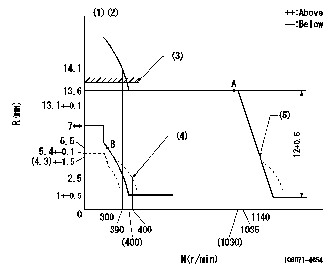
N:Pump speed
R:Rack position (mm)
(1)Tolerance for racks not indicated: +-0.05mm.
(2)Set the load lever's stop position so that R = aa (N = 0).
(3)Rack limit using the stop lever: R1
(4)Damper spring setting
(5)Injection quantity Q = Q1
----------
aa=5.4+-0.1mm R1=13.9+-0.1mm Q1=(18)+-1.5mm3/st
----------
----------
aa=5.4+-0.1mm R1=13.9+-0.1mm Q1=(18)+-1.5mm3/st
----------
Speed control lever angle

F:Full speed
----------
----------
a=(2.5deg)+-5deg
----------
----------
a=(2.5deg)+-5deg
0000000901
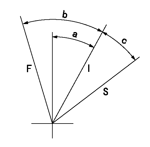
F:Full load
I:Idle
S:Stop
----------
----------
a=20deg+-5deg b=46.5deg+-3deg c=(10deg)+-5deg
----------
----------
a=20deg+-5deg b=46.5deg+-3deg c=(10deg)+-5deg
Stop lever angle
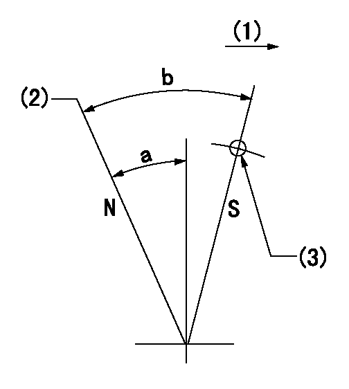
N:Pump normal
S:Stop the pump.
(1)Drive side
(2)Rack position = aa
(3)Use the hole at R = bb
----------
aa=13.9+-0.1mm bb=50mm
----------
a=34deg+-5deg b=36deg+-5deg
----------
aa=13.9+-0.1mm bb=50mm
----------
a=34deg+-5deg b=36deg+-5deg
Timing setting

(1)Pump vertical direction
(2)Coupling's key groove position at No 1 cylinder's beginning of injection
(3)-
(4)-
----------
----------
a=(7deg)
----------
----------
a=(7deg)
Information:
Connect the wiring harness to a voltage source of 12 VOLTS maximum with a negative ground only. Install the additive tank on the outside of the engine compartment.
Connect the wiring to 8L5000 Switch (1) so that the system can be activated with the starting motor switch in the OFF position. Keep the additive tank full when not in use. This will prevent damage to the system and components by corrosion when not used for long periods of time.Operation: Just before the engine is started, push the switch to activate the system; this will let the additive flow for approximately two minutes, through an orifice connected to the fuel supply line of the Sleeve Metering Fuel System. The fuel transfer pump then pulls the additive into the system along with the Diesel fuel. The system can be again activated if necessary. The engine can be started approximately three to four times per liter (fifteen to twenty times per gallon) of additive.Maintenance: Keep the additive tank full when not in use. This will prevent damage to the system and components by corrosion when not used for long periods of time. Install a new injection group filter (9N3778) at six month intervals or when the filter becomes plugged (full of foreign material) so additive will not flow through it. ADDITIVE RECOMMENDATION: Ethyl D112 Diesel Ignition Improver AVAILABLE SOURCE:U.S.A.
Ethyl Corporation
Distribution Service
Petroleum Chemical Division
451 Florida Boulevard
Baton Rouge, Lousiana 70801
CANADA
Ethyl Corporation of Canada, Ltd.
48 St. Clair Avenue West
Toronto, Ontario, Canada M4V1M7
Order Department
Ethyl D11-2 Diesel Ignition Improver is highly flammable; do not install the additive tank near a source of heat or sparks. If there is a leak in the tank or an accident causes a loss of additive, a fire could be the result.
1 - 9N3334 Tank Assembly2 - 1P4022 Fitting3 - 9N3778 Filter Assembly4 - 8L6557 Connector5 - 317224 Hose Assembly6 - 306984 Connector7 - 9L8791 Solenoid8 - 7W1539 Orifice9 - 8T2543 Tee10 - 5P5009 Reducer11 - 9N3828 Harness Assembly12 - 7G1018 Relay13 - 8L5000 Switch14 - 9N3335 Strap 533567 Bracket15 - 5P0733 Hose 200 (8.0")16 - 1P4278 Clamp17 - 7D1553 Clip18 - 8J1256 Clip19 - 4B1248 Screw 4B2051 Nut 4B4674 Washer20 - 3J7354 Seal21 - 1J9671 Seal1 Install items (12) and (13) inside the operator's compartment; fasten switch (13) on the dash and install relay (12) under the dash. Install additive tank (1) on the outside of the engine compartment in an acceptable location for easy access and away from any source of heat.2 Install 9N3620 Fuel Additive Injection Instruction Film on the dash next to 8L5000 Switch (13). Install 9N3621 CAUTION Film on tank (1) at a location that can be seen from the side of the vehicle.3 Install the remainder of the parts as shown in the above illustration. Fasten filter (3), and hoses (5) and (15) with the clips shown.4 Check the system for leaks after the installation is complete; use air at a maximum pressure of 70 to 105 kPa (10 to 15 psi).