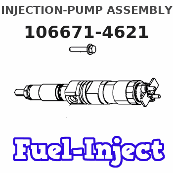
Information injection-pump assembly
BOSCH
9 400 616 818
9400616818
ZEXEL
106671-4621
1066714621
MITSUBISHI-HEAV
3626550180
3626550180
Rating:
Service parts 106671-4621 INJECTION-PUMP ASSEMBLY:
1.
_
7.
COUPLING PLATE
8.
_
9.
_
10.
NOZZLE AND HOLDER ASSY
11.
Nozzle and Holder
12.
Open Pre:MPa(Kqf/cm2)
13.
NOZZLE-HOLDER
14.
NOZZLE
15.
NOZZLE SET
Include in #1:
106671-4621
as INJECTION-PUMP ASSEMBLY
Cross reference number
BOSCH
9 400 616 818
9400616818
ZEXEL
106671-4621
1066714621
MITSUBISHI-HEAV
3626550180
3626550180
Zexel num
Bosch num
Firm num
Name
9 400 616 818
3626550180 MITSUBISHI-HEAV
INJECTION-PUMP ASSEMBLY
S6B K 14CA INJECTION PUMP ASSY PE6P,6PD PE
S6B K 14CA INJECTION PUMP ASSY PE6P,6PD PE
Calibration Data:
Adjustment conditions
Test oil
1404 Test oil ISO4113 or {SAEJ967d}
1404 Test oil ISO4113 or {SAEJ967d}
Test oil temperature
degC
40
40
45
Nozzle and nozzle holder
105780-8130
Bosch type code
EFEP215A
Nozzle
105780-0050
Bosch type code
DN6TD119NP1T
Nozzle holder
105780-2090
Bosch type code
EFEP215
Opening pressure
MPa
17.2
Opening pressure
kgf/cm2
175
Injection pipe
Outer diameter - inner diameter - length (mm) mm 8-3-600
Outer diameter - inner diameter - length (mm) mm 8-3-600
Overflow valve
131424-7420
Overflow valve opening pressure
kPa
255
221
289
Overflow valve opening pressure
kgf/cm2
2.6
2.25
2.95
Tester oil delivery pressure
kPa
157
157
157
Tester oil delivery pressure
kgf/cm2
1.6
1.6
1.6
Direction of rotation (viewed from drive side)
Right R
Right R
Injection timing adjustment
Direction of rotation (viewed from drive side)
Right R
Right R
Injection order
1-5-3-6-
2-4
Pre-stroke
mm
3.9
3.85
3.95
Beginning of injection position
Governor side NO.1
Governor side NO.1
Difference between angles 1
Cal 1-5 deg. 60 59.5 60.5
Cal 1-5 deg. 60 59.5 60.5
Difference between angles 2
Cal 1-3 deg. 120 119.5 120.5
Cal 1-3 deg. 120 119.5 120.5
Difference between angles 3
Cal 1-6 deg. 180 179.5 180.5
Cal 1-6 deg. 180 179.5 180.5
Difference between angles 4
Cyl.1-2 deg. 240 239.5 240.5
Cyl.1-2 deg. 240 239.5 240.5
Difference between angles 5
Cal 1-4 deg. 300 299.5 300.5
Cal 1-4 deg. 300 299.5 300.5
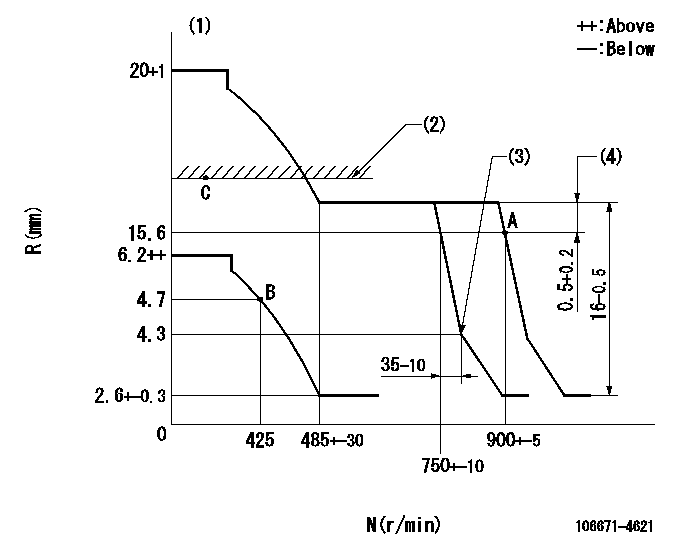
Injection quantity adjustment
Adjusting point
A
Rack position
15.6
Pump speed
r/min
900
900
900
Average injection quantity
mm3/st.
333
326
340
Max. variation between cylinders
%
0
-3
3
Basic
*
Fixing the rack
*
Injection quantity adjustment_02
Adjusting point
B
Rack position
4.7+-0.5
Pump speed
r/min
425
425
425
Average injection quantity
mm3/st.
32.2
29.7
34.7
Max. variation between cylinders
%
0
-10
10
Fixing the rack
*
Timer adjustment
Pump speed
r/min
450--
Advance angle
deg.
0
0
0
Remarks
Start
Start
Timer adjustment_02
Pump speed
r/min
400
Advance angle
deg.
0.5
Timer adjustment_03
Pump speed
r/min
850
Advance angle
deg.
2
1.5
2.5
Remarks
Finish
Finish
Test data Ex:
Governor adjustment
N:Pump speed
R:Rack position (mm)
(1)Target notch: K
(2)RACK LIMIT: RAL
(3)Idle sub spring setting: L1.
(4)Rack difference between N = N1 and N = N2
----------
K=4 RAL=16.6+0.2mm L1=4.3-0.5mm N1=900r/min N2=850r/min
----------
----------
K=4 RAL=16.6+0.2mm L1=4.3-0.5mm N1=900r/min N2=850r/min
----------
Speed control lever angle
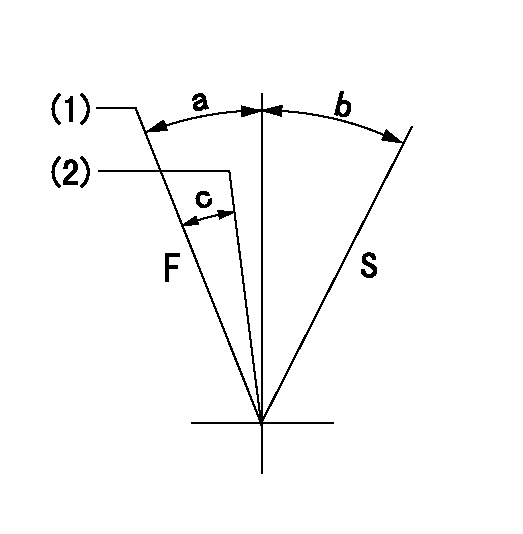
F:Full speed
S:Stop
(1)Set the pump speed at aa. ( At delivery )
(2)Set the pump speed at bb.
----------
aa=900r/min bb=750r/min
----------
a=6deg+-5deg b=29deg+-3deg c=6deg+-5deg
----------
aa=900r/min bb=750r/min
----------
a=6deg+-5deg b=29deg+-3deg c=6deg+-5deg
0000000901
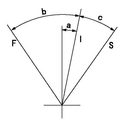
F:Full load
I:Idle
S:Stop
----------
----------
a=(5deg)+-5deg b=(28deg)+-5deg c=(41deg)+-5deg
----------
----------
a=(5deg)+-5deg b=(28deg)+-5deg c=(41deg)+-5deg
Timing setting

(1)Pump vertical direction
(2)Coupling's key groove position at No 1 cylinder's beginning of injection
(3)-
(4)-
----------
----------
a=(90deg)
----------
----------
a=(90deg)
Information:
When using an external electrical source to start your engine: turn the START switch off, remove the key, and turn off all electrical accessories before attaching cables.When using jumper cables always connect the POSITIVE (+) cable to the POSITIVE (+) terminal of the battery connected to the starter solenoid. Connect the NEGATIVE (-) cable from the external source to the starter NEGATIVE (-) terminal. If not equipped with a starter NEGATIVE terminal, connect to the engine block.Do not reverse the battery cables. The alternator can be damaged. Attach the ground cable last and remove first.
1. Connect one end of the cable to the POSITIVE (+) terminal of the battery being started. Connect the other end to the POSITIVE (+) terminal of the power source.2. Connect one of the other cable to the NEGATIVE (-) terminal of the power source. Connect the other end to starter NEGATIVE (-) terminal or to the engine block. This prevents potential sparks from igniting combustible gases produced by some batteries.3. Start the engine.4. After the engine starts, disconnect the cable from the starter NEGATIVE (-) terminal or engine block. Disconnect the other end from the NEGATIVE (-) terminal of the power source.5. Disconnect the cable from the POSITIVE (+) terminal of the battery on the engine being started. Disconnect the cable from the POSITIVE (+) terminal of the power source.Air Starting
For good life of the air starting motor, the air supply must be free of dirt and water. A lubricator must be used with the starting system. Use non detergent 10W engine oil for temperatures that are greater than 0°C (32°F) or use air tool oil for lower temperatures.1. Open and close the drain valve on the bottom of the air tank to drain condensation and oil carryover.2. Check the air supply pressure. The air starting motor requires a minimum of 690 kPa (100 psi) air pressure to operate properly. The maximum air pressure must not exceed 1550 kPa (225 psi). The normal air pressure will be 758 to 965 kPa (110 to 140 psi).
Air Starter showing Air Valve (1) and Lubricator Bowl (2)3. Check the oil level in the lubricator bowl (2). Keep the bowl at least half full and add lubricant if necessary.4. Push the air valve (1) or the engine start button to crank the engine. Release the valve or button as soon as the engine starts.Cold Weather Starting Aids
Personal injury or death can result from using ether.Personal injury or property damage can result from alcohol or starting fluids. Alcohol or starting fluids are highly flammable and toxic and if improperly stored could result in injury or property damage.When using starting fluid, follow the manufacturer's instructions carefully. Use ether sparingly and spray it only while cranking the engine.Failure to follow these instructions could result in an explosion and/or fire and possible personal injury.
Excessive ether can cause piston and ring damage. Use ether for cold starting purposes only. Do not use excessive starting fluid during starting or after the engine is