Information injection-pump assembly
BOSCH
9 400 616 814
9400616814
ZEXEL
106671-4560
1066714560
KOMATSU
6152711340
6152711340
Rating:
Service parts 106671-4560 INJECTION-PUMP ASSEMBLY:
1.
_
7.
COUPLING PLATE
8.
_
9.
_
11.
Nozzle and Holder
12.
Open Pre:MPa(Kqf/cm2)
24.5(250)
15.
NOZZLE SET
Include in #1:
106671-4560
as INJECTION-PUMP ASSEMBLY
Cross reference number
BOSCH
9 400 616 814
9400616814
ZEXEL
106671-4560
1066714560
KOMATSU
6152711340
6152711340
Zexel num
Bosch num
Firm num
Name
106671-4560
9 400 616 814
6152711340 KOMATSU
INJECTION-PUMP ASSEMBLY
SA6D125 K 14CA INJECTION PUMP ASSY PE6P,6PD PE
SA6D125 K 14CA INJECTION PUMP ASSY PE6P,6PD PE
Calibration Data:
Adjustment conditions
Test oil
1404 Test oil ISO4113 or {SAEJ967d}
1404 Test oil ISO4113 or {SAEJ967d}
Test oil temperature
degC
40
40
45
Nozzle and nozzle holder
105780-8140
Bosch type code
EF8511/9A
Nozzle
105780-0000
Bosch type code
DN12SD12T
Nozzle holder
105780-2080
Bosch type code
EF8511/9
Opening pressure
MPa
17.2
Opening pressure
kgf/cm2
175
Injection pipe
Outer diameter - inner diameter - length (mm) mm 8-3-600
Outer diameter - inner diameter - length (mm) mm 8-3-600
Overflow valve opening pressure
kPa
157
123
191
Overflow valve opening pressure
kgf/cm2
1.6
1.25
1.95
Tester oil delivery pressure
kPa
157
157
157
Tester oil delivery pressure
kgf/cm2
1.6
1.6
1.6
Direction of rotation (viewed from drive side)
Left L
Left L
Injection timing adjustment
Direction of rotation (viewed from drive side)
Left L
Left L
Injection order
1-5-3-6-
2-4
Pre-stroke
mm
3.8
3.75
3.85
Beginning of injection position
Drive side NO.1
Drive side NO.1
Difference between angles 1
Cal 1-5 deg. 60 59.5 60.5
Cal 1-5 deg. 60 59.5 60.5
Difference between angles 2
Cal 1-3 deg. 120 119.5 120.5
Cal 1-3 deg. 120 119.5 120.5
Difference between angles 3
Cal 1-6 deg. 180 179.5 180.5
Cal 1-6 deg. 180 179.5 180.5
Difference between angles 4
Cyl.1-2 deg. 240 239.5 240.5
Cyl.1-2 deg. 240 239.5 240.5
Difference between angles 5
Cal 1-4 deg. 300 299.5 300.5
Cal 1-4 deg. 300 299.5 300.5
Injection quantity adjustment
Adjusting point
A
Rack position
11.1
Pump speed
r/min
1050
1050
1050
Average injection quantity
mm3/st.
179.1
177.1
181.1
Max. variation between cylinders
%
0
-3
3
Basic
*
Fixing the lever
*
Boost pressure
kPa
40
40
Boost pressure
mmHg
300
300
Injection quantity adjustment_02
Adjusting point
B
Rack position
11.1
Pump speed
r/min
700
700
700
Average injection quantity
mm3/st.
182.1
178.1
186.1
Max. variation between cylinders
%
0
-4
4
Fixing the lever
*
Boost pressure
kPa
40
40
Boost pressure
mmHg
300
300
Injection quantity adjustment_03
Adjusting point
C
Rack position
3.7+-0.5
Pump speed
r/min
425
425
425
Average injection quantity
mm3/st.
13
11.5
14.5
Max. variation between cylinders
%
0
-15
15
Fixing the rack
*
Boost pressure
kPa
0
0
0
Boost pressure
mmHg
0
0
0
Boost compensator adjustment
Pump speed
r/min
650
650
650
Rack position
9.3
Boost pressure
kPa
6.7
5.4
8
Boost pressure
mmHg
50
40
60
Boost compensator adjustment_02
Pump speed
r/min
650
650
650
Rack position
11.1
Boost pressure
kPa
26.7
20
33.4
Boost pressure
mmHg
200
150
250
Timer adjustment
Pump speed
r/min
650
Advance angle
deg.
0.5
Timer adjustment_02
Pump speed
r/min
850
Advance angle
deg.
1.2
0.7
1.7
Timer adjustment_03
Pump speed
r/min
1050
Advance angle
deg.
3
2.5
3.5
Remarks
Finish
Finish
Test data Ex:
Governor adjustment
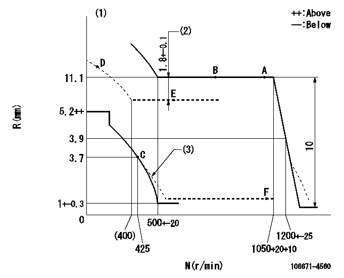
N:Pump speed
R:Rack position (mm)
(1)Deliver without the torque control spring operating.
(2)Boost compensator stroke
(3)Damper spring setting: DL
----------
DL=3.6-0.5mm
----------
----------
DL=3.6-0.5mm
----------
Speed control lever angle

F:Full speed
----------
----------
a=18deg+-5deg
----------
----------
a=18deg+-5deg
0000000901

F:Full load
I:Idle
(1)Stopper bolt setting
----------
----------
a=10deg+-5deg b=37deg+-3deg
----------
----------
a=10deg+-5deg b=37deg+-3deg
Stop lever angle

N:Pump normal
S:Stop the pump.
----------
----------
a=32deg+-5deg b=64deg+-5deg
----------
----------
a=32deg+-5deg b=64deg+-5deg
Timing setting

(1)Pump vertical direction
(2)Coupling's key groove position at No 1 cylinder's beginning of injection
(3)-
(4)-
----------
----------
a=(150deg)
----------
----------
a=(150deg)
Information:
You must read and understand the warnings and instructions contained in the Safety section of this manual, before performing any operation or maintenance procedures.Cooling System
Do not perform this maintenance until you read and understand the material in the Safety and Cooling System Specifications sections of this publication.
Drain/Flush/Replace Coolant (Long Life Coolant/Antifreeze Only)
Caterpillar Long Life Coolant/Antifreeze should be replaced every 6,000 Service Hours or 4 Years, whichever comes first. Only clean water is needed to clean and flush the cooling system when LLCA is drained and replaced.Drain
1. Stop the engine and allow the engine to cool. Loosen the coolant filler cap slowly to relieve any pressure, and remove the cap.2. Remove the radiator drain plug, or open the radiator drain valve (if equipped). Remove the block and oil cooler drain plugs. Remove the drain plug from the bottom of the water pump housing. Allow the coolant to drain.
Dispose of used engine coolant properly or recycle. Various methods have been proposed to reclaim used coolant for reuse in engine cooling systems. The full distillation procedure is the only method acceptable by Caterpillar to reclaim the used coolant. Contact your Caterpillar for information regarding disposal and recycling of used coolant.
For information regarding disposal and recycling of used coolant:Contact Caterpillar Service Technology Group:Outside Illinois: 1-800-542-TOOLInside Illinois: 1-800-541-TOOLCanada: 1-800-523-TOOLFlush
4. Flush the cooling system with clean water to remove any debris.5. Clean and install all drain plugs and/or close the drain valve(s).6. Fill the cooling system with clean water. Install the filler cap. Operate the engine until warm 49 to 66°C (150 to 120°F).7. Stop the engine and allow the engine to cool. Loosen the coolant filler cap slowly to relieve any pressure, and remove the cap. Remove the cooling system drain plug(s) or open the drain valve. Allow the water to drain. Flush the cooling system with clean water.8. Repeat steps 6 and 7.Fill
9. Fill the cooling system with LLCA. Refer to the refill capacities chart in this manual for the amount of LLCA needed to refill your system.10. Start and run the engine with the filler cap removed. Allow the LLCA to warm, the thermostat to open, and the coolant level to stabilize. Add LLCA if necessary to bring the coolant to the proper level.11. Check the condition of the filler cap gasket. If the gasket is damaged, discard the old filler cap and install a new filler cap. If the gasket is not damaged, use a 9S8140 Service Tool (available from your Caterpillar dealer) to pressure test the filler cap. The correct filler cap pressure is stamped on the face of the filler cap. If the filler cap does not hold the correct pressure, install a new filler cap.12. Start the engine and inspect for coolant leaks and proper operating temperature.
Have questions with 106671-4560?
Group cross 106671-4560 ZEXEL
Mitsubishi-Heav
Niigata-Urawa
Niigata-Urawa
Niigata-Tekkou
Mitsubishi-Heav
Komatsu
106671-4560
9 400 616 814
6152711340
INJECTION-PUMP ASSEMBLY
SA6D125
SA6D125