Information injection-pump assembly
BOSCH
9 400 616 813
9400616813
ZEXEL
106671-4550
1066714550
KOMATSU
6151711380
6151711380
Rating:
Service parts 106671-4550 INJECTION-PUMP ASSEMBLY:
1.
_
7.
COUPLING PLATE
8.
_
9.
_
11.
Nozzle and Holder
12.
Open Pre:MPa(Kqf/cm2)
24.5(250)
15.
NOZZLE SET
Include in #1:
106671-4550
as INJECTION-PUMP ASSEMBLY
Cross reference number
BOSCH
9 400 616 813
9400616813
ZEXEL
106671-4550
1066714550
KOMATSU
6151711380
6151711380
Zexel num
Bosch num
Firm num
Name
106671-4550
9 400 616 813
6151711380 KOMATSU
INJECTION-PUMP ASSEMBLY
S6D125 K
S6D125 K
Calibration Data:
Adjustment conditions
Test oil
1404 Test oil ISO4113 or {SAEJ967d}
1404 Test oil ISO4113 or {SAEJ967d}
Test oil temperature
degC
40
40
45
Nozzle and nozzle holder
105780-8140
Bosch type code
EF8511/9A
Nozzle
105780-0000
Bosch type code
DN12SD12T
Nozzle holder
105780-2080
Bosch type code
EF8511/9
Opening pressure
MPa
17.2
Opening pressure
kgf/cm2
175
Injection pipe
Outer diameter - inner diameter - length (mm) mm 8-3-600
Outer diameter - inner diameter - length (mm) mm 8-3-600
Overflow valve opening pressure
kPa
157
123
191
Overflow valve opening pressure
kgf/cm2
1.6
1.25
1.95
Tester oil delivery pressure
kPa
157
157
157
Tester oil delivery pressure
kgf/cm2
1.6
1.6
1.6
Direction of rotation (viewed from drive side)
Left L
Left L
Injection timing adjustment
Direction of rotation (viewed from drive side)
Left L
Left L
Injection order
1-5-3-6-
2-4
Pre-stroke
mm
3.8
3.75
3.85
Beginning of injection position
Drive side NO.1
Drive side NO.1
Difference between angles 1
Cal 1-5 deg. 60 59.5 60.5
Cal 1-5 deg. 60 59.5 60.5
Difference between angles 2
Cal 1-3 deg. 120 119.5 120.5
Cal 1-3 deg. 120 119.5 120.5
Difference between angles 3
Cal 1-6 deg. 180 179.5 180.5
Cal 1-6 deg. 180 179.5 180.5
Difference between angles 4
Cyl.1-2 deg. 240 239.5 240.5
Cyl.1-2 deg. 240 239.5 240.5
Difference between angles 5
Cal 1-4 deg. 300 299.5 300.5
Cal 1-4 deg. 300 299.5 300.5
Injection quantity adjustment
Adjusting point
A
Rack position
9.5
Pump speed
r/min
1050
1050
1050
Average injection quantity
mm3/st.
134.9
132.9
136.9
Max. variation between cylinders
%
0
-3
3
Basic
*
Fixing the lever
*
Boost pressure
kPa
46.7
46.7
Boost pressure
mmHg
350
350
Injection quantity adjustment_02
Adjusting point
B
Rack position
10.7
Pump speed
r/min
700
700
700
Average injection quantity
mm3/st.
166
164
168
Max. variation between cylinders
%
0
-4
4
Fixing the lever
*
Boost pressure
kPa
46.7
46.7
Boost pressure
mmHg
350
350
Injection quantity adjustment_03
Adjusting point
C
Rack position
3.9+-0.5
Pump speed
r/min
425
425
425
Average injection quantity
mm3/st.
13
11.5
14.5
Max. variation between cylinders
%
0
-15
15
Fixing the rack
*
Boost pressure
kPa
0
0
0
Boost pressure
mmHg
0
0
0
Boost compensator adjustment
Pump speed
r/min
650
650
650
Rack position
8.3
Boost pressure
kPa
6.7
5.4
8
Boost pressure
mmHg
50
40
60
Boost compensator adjustment_02
Pump speed
r/min
650
650
650
Rack position
10.7
Boost pressure
kPa
33.3
26.6
40
Boost pressure
mmHg
250
200
300
Timer adjustment
Pump speed
r/min
650
Advance angle
deg.
0.5
Timer adjustment_02
Pump speed
r/min
850
Advance angle
deg.
1.2
0.7
1.7
Timer adjustment_03
Pump speed
r/min
1050
Advance angle
deg.
3
2.5
3.5
Remarks
Finish
Finish
Test data Ex:
Governor adjustment
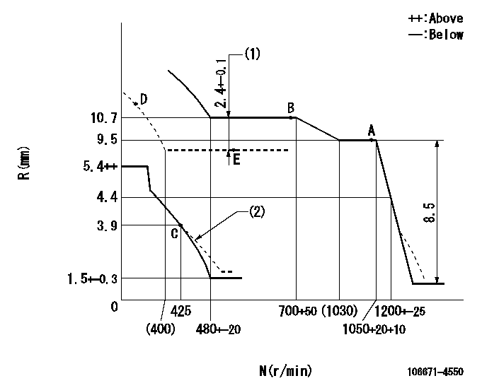
N:Pump speed
R:Rack position (mm)
(1)Boost compensator stroke
(2)Damper spring setting: DL
----------
DL=3.8-0.5mm
----------
----------
DL=3.8-0.5mm
----------
Speed control lever angle

F:Full speed
----------
----------
a=18deg+-5deg
----------
----------
a=18deg+-5deg
0000000901

F:Full load
I:Idle
(1)Stopper bolt setting
----------
----------
a=10deg+-5deg b=34deg+-3deg
----------
----------
a=10deg+-5deg b=34deg+-3deg
Stop lever angle

N:Pump normal
S:Stop the pump.
----------
----------
a=32deg+-5deg b=64deg+-5deg
----------
----------
a=32deg+-5deg b=64deg+-5deg
Timing setting

(1)Pump vertical direction
(2)Coupling's key groove position at No 1 cylinder's beginning of injection
(3)-
(4)-
----------
----------
a=(150deg)
----------
----------
a=(150deg)
Information:
Jacket Water Pump
A failed water pump might cause severe engine overheating problems that could result in cracks in the cylinder head, a piston seizure or other potential damage to the engine.Visually inspect the water pump for leaks. If leaking is observed, replace all seals. Refer to the Service Manual for the procedure to replace the seals.Turbocharger
Refer to the Turbocharger topic in the Every 3000 Hours maintenance interval for information regarding turbocharger inspection. Refer to the Service Manual, or consult with your Caterpillar dealer for the complete turbocharger inspection procedure.Alternator and Starting Motor
Caterpillar recommends a scheduled inspection of the alternator. Inspect the alternator for loose connections and proper battery charging. Inspect the ammeter gauge during engine operation to ensure the batteries and/or electrical system is performing correctly. Make repairs as necessary. Refer to the Service Manual.Check the alternator and battery charger for proper operation. If the batteries are properly charged, ammeter reading should be very near zero. All batteries should be kept charged. The batteries should be kept warm because temperature affects the cranking power. If the battery is too cold, it will not crank the engine, even if the engine is warm.When the engine is not run for long periods of time or run for short periods, the batteries may not fully recharge. Ensure the alternator performs properly to charge the battery and to help prevent the battery from freezing.If the starting motor fails, the engine may not start in an emergency situation. Caterpillar recommends a schedule inspection/check of your starting motor. The starting motor should be checked for correct operation. All electrical connections should be cleaned and checked. Refer to the established procedure for inspection and specifications in the Service Manual, or contact your Caterpillar dealer for assistance.Repair Before Failure
Until recently, engine maintenance and repair management involved changing the oil when it was convenient and repairing the engine when it was damaged. This seemed to be the accepted way of managing a maintenance operation.However, due to a variety of circumstances, increasing competition have caused users to look for ways to prolong equipment life and lower operating costs so that they could be competitive.To assist Caterpillar engine users in prolonging engine life and reducing operating costs, the Value Planned Repair approach to engine maintenance was developed.The Value Planned Repair approach can be tailored for any engine. This approach, when properly structured, outlines every maintenance and repair service required to support an engine from the day it enters service until the day it is retired.To ensure the repair is performed efficiently and expediently, the Value Planned Repair concept approaches a given repair in three basis steps:1. Repair determination2. Evaluation of repair options3. Selection of the most appropriate optionThe Value Planned Repair approach addresses:* Services required to maintain an engine at optimum efficiency.* Scheduled maintenance, repairs and overhauls to minimize unscheduled downtime.* Preplanned repairs and overhauls that can be flat-rated, putting you in charge of costs.* Repair
Have questions with 106671-4550?
Group cross 106671-4550 ZEXEL
Mitsubishi-Heav
Niigata-Urawa
Niigata-Urawa
Niigata-Tekkou
Mitsubishi-Heav
Komatsu
106671-4550
9 400 616 813
6151711380
INJECTION-PUMP ASSEMBLY
S6D125
S6D125