Information injection-pump assembly
ZEXEL
106671-4542
1066714542
MITSUBISHI-HEAV
3626530161
3626530161
Rating:
Service parts 106671-4542 INJECTION-PUMP ASSEMBLY:
1.
_
7.
COUPLING PLATE
8.
_
9.
_
10.
NOZZLE AND HOLDER ASSY
11.
Nozzle and Holder
12.
Open Pre:MPa(Kqf/cm2)
21.6{220}
15.
NOZZLE SET
Include in #1:
106671-4542
as INJECTION-PUMP ASSEMBLY
Cross reference number
ZEXEL
106671-4542
1066714542
MITSUBISHI-HEAV
3626530161
3626530161
Zexel num
Bosch num
Firm num
Name
Calibration Data:
Adjustment conditions
Test oil
1404 Test oil ISO4113 or {SAEJ967d}
1404 Test oil ISO4113 or {SAEJ967d}
Test oil temperature
degC
40
40
45
Nozzle and nozzle holder
105780-8130
Bosch type code
EFEP215A
Nozzle
105780-0050
Bosch type code
DN6TD119NP1T
Nozzle holder
105780-2090
Bosch type code
EFEP215
Opening pressure
MPa
17.2
Opening pressure
kgf/cm2
175
Injection pipe
Outer diameter - inner diameter - length (mm) mm 8-3-600
Outer diameter - inner diameter - length (mm) mm 8-3-600
Overflow valve opening pressure
kPa
157
123
191
Overflow valve opening pressure
kgf/cm2
1.6
1.25
1.95
Tester oil delivery pressure
kPa
157
157
157
Tester oil delivery pressure
kgf/cm2
1.6
1.6
1.6
Direction of rotation (viewed from drive side)
Right R
Right R
Injection timing adjustment
Direction of rotation (viewed from drive side)
Right R
Right R
Injection order
1-5-3-6-
2-4
Pre-stroke
mm
3.7
3.65
3.75
Beginning of injection position
Governor side NO.1
Governor side NO.1
Difference between angles 1
Cal 1-5 deg. 60 59.5 60.5
Cal 1-5 deg. 60 59.5 60.5
Difference between angles 2
Cal 1-3 deg. 120 119.5 120.5
Cal 1-3 deg. 120 119.5 120.5
Difference between angles 3
Cal 1-6 deg. 180 179.5 180.5
Cal 1-6 deg. 180 179.5 180.5
Difference between angles 4
Cyl.1-2 deg. 240 239.5 240.5
Cyl.1-2 deg. 240 239.5 240.5
Difference between angles 5
Cal 1-4 deg. 300 299.5 300.5
Cal 1-4 deg. 300 299.5 300.5
Injection quantity adjustment
Adjusting point
A
Rack position
10.6
Pump speed
r/min
600
600
600
Average injection quantity
mm3/st.
278.2
271.2
285.2
Max. variation between cylinders
%
0
-3
3
Basic
*
Fixing the rack
*
Injection quantity adjustment_02
Adjusting point
B
Rack position
4.6+-0.5
Pump speed
r/min
425
425
425
Average injection quantity
mm3/st.
20.6
18.1
23.1
Max. variation between cylinders
%
0
-10
10
Fixing the rack
*
Injection quantity adjustment_03
Adjusting point
C
Rack position
-
Pump speed
r/min
100
100
100
Average injection quantity
mm3/st.
243
243
253
Fixing the lever
*
Rack limit
*
Timer adjustment
Pump speed
r/min
(450--)
Advance angle
deg.
0
0
0
Remarks
Start
Start
Timer adjustment_02
Pump speed
r/min
400
Advance angle
deg.
0.5
Timer adjustment_03
Pump speed
r/min
500
Advance angle
deg.
0.9
Timer adjustment_04
Pump speed
r/min
550
Advance angle
deg.
1
0.5
1.5
Timer adjustment_05
Pump speed
r/min
-
Advance angle
deg.
4
3.5
4.5
Remarks
Finish
Finish
Test data Ex:
Governor adjustment
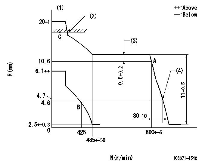
N:Pump speed
R:Rack position (mm)
(1)Target notch: K
(2)RACK LIMIT
(3)Rack difference between N = N1 and N = N2
(4)Idle sub spring setting: L1.
----------
K=18 N1=600r/min N2=550r/min L1=4.7-0.5mm
----------
----------
K=18 N1=600r/min N2=550r/min L1=4.7-0.5mm
----------
Speed control lever angle
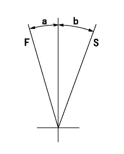
F:Full speed
S:Stop
----------
----------
a=(19deg)+-5deg b=32deg+-3deg
----------
----------
a=(19deg)+-5deg b=32deg+-3deg
0000000901
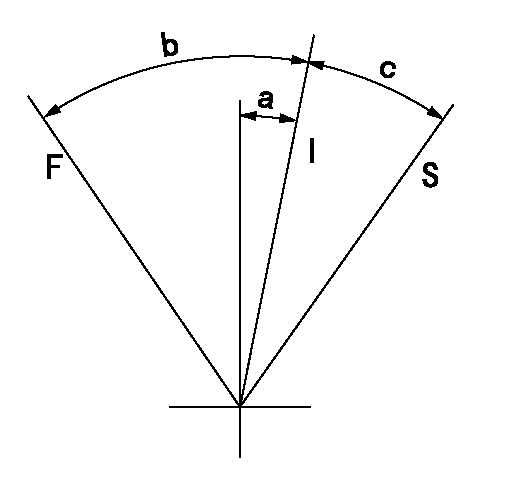
F:Full load
I:Idle
S:Stop
----------
----------
a=(1deg)+-5deg b=(20deg)+-5deg c=(41deg)+-5deg
----------
----------
a=(1deg)+-5deg b=(20deg)+-5deg c=(41deg)+-5deg
Timing setting

(1)Pump vertical direction
(2)Coupling's key groove position at No 1 cylinder's beginning of injection
(3)-
(4)-
----------
----------
a=(100deg)
----------
----------
a=(100deg)
Information:
Turbocharger
Turbocharger bearing failures can cause large quantities of oil to enter the air intake and exhaust systems. Loss of engine lubricant can result in serious engine damage.Minor leakage of a turbocharger housing under extended low idle operation will not cause problems as long as a turbocharger bearing failure has NOT occurred.When a turbocharger bearing failure is accomplished by a significant engine performance loss (exhaust smoke or engine speed up at no load), DO NOT continue engine operation until the turbocharger is repaired or replaced.
An inspection/check of your turbocharger will minimize unscheduled downtime and reduce the chance for potential damage to other engine parts.Inspect/Check
1. Remove the exhaust outlet and air inlet piping from the turbocharger. Visually check for oil leaks.2. Turn the turbine and compressor wheel by hand. The assembly should turn freely.3. Inspect the turbine wheel and compressor wheel for contact with the turbocharger housing. There should NOT be any visible signs of contact between the turbine or compressor wheels and the turbocharger housing.4. Check the compressor wheel for cleanliness. If only the blade side of the wheel is dirty, dirt and/or moisture is passing through the air filtering system. If oil is found only on the back side of the wheel, it indicates a possible turbocharger oil seal leak.The leak may be the result of extended engine operation at low idle or an intake air line restriction (plugged air filters), which causes the turbocharger to "slobber".* Maintain the compressor wheel/turbine housing by cleaning with standard shop solvents and a soft bristle brush.5. Check the end play and bearing clearance on the turbine wheel and shaft. If the measurements are not within specifications (see the Service Manual), the turbocharger must be repaired or replaced.6. When installing or replacing V-band clamps, position the gap (tightening screw) down if possible so any accumulation of moisture will drain away. Turbocharger components require precision clearances and balancing due to operation at high rotation (torsional) speeds. Severe Service Applications can accelerate component wear and may suggest the need to Inspect/Repair/Replace the cartridge at reduced intervals to ensure maximum reliability and retention of the full core.Removal and Installation
For removal and installation, or repair/replacement options of turbochargers, see your Caterpillar dealer. Refer to the Service Manual for this engine or consult your Caterpillar dealer for the procedure and specifications.Engine Mounts and Crankshaft Vibration Damper
Inspect/Check Engine Mounts
Caterpillar recommends checking the engine mounts for deterioration and proper bolt torque. This will prevent excessive engine vibration caused from improper mounting. See your Service Manual or Caterpillar dealer for recommended torque values.Inspect/Check Camshaft Vibration Damper
Damage to, or failure of the damper will increase torsional vibrations and result in damage to the crankshaft and other engine components. A deteriorating vibration damper will cause excessive gear train noise at variable points in the engine speed range.Rubber Damper
Your engine may be equipped with a standard Rubber Crankshaft Torsional Vibration Damper. A standard damper uses a rubber mounted ring to reduce crankshaft vibration. Some engines also have a Visconic Torsional Vibration Damper. A