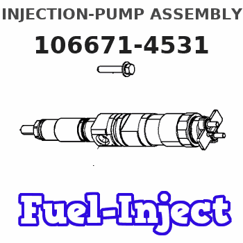
Information injection-pump assembly
ZEXEL
106671-4531
1066714531
Rating:
Service parts 106671-4531 INJECTION-PUMP ASSEMBLY:
1.
_
7.
COUPLING PLATE
8.
_
9.
_
11.
Nozzle and Holder
12.
Open Pre:MPa(Kqf/cm2)
25.5{260}
15.
NOZZLE SET
Include in #1:
106671-4531
as INJECTION-PUMP ASSEMBLY
Cross reference number
ZEXEL
106671-4531
1066714531
Zexel num
Bosch num
Firm num
Name
106671-4531
INJECTION-PUMP ASSEMBLY
Calibration Data:
Adjustment conditions
Test oil
1404 Test oil ISO4113 or {SAEJ967d}
1404 Test oil ISO4113 or {SAEJ967d}
Test oil temperature
degC
40
40
45
Nozzle and nozzle holder
105780-8140
Bosch type code
EF8511/9A
Nozzle
105780-0000
Bosch type code
DN12SD12T
Nozzle holder
105780-2080
Bosch type code
EF8511/9
Opening pressure
MPa
17.2
Opening pressure
kgf/cm2
175
Injection pipe
Outer diameter - inner diameter - length (mm) mm 8-3-600
Outer diameter - inner diameter - length (mm) mm 8-3-600
Overflow valve
131425-0120
Overflow valve opening pressure
kPa
157
123
191
Overflow valve opening pressure
kgf/cm2
1.6
1.25
1.95
Tester oil delivery pressure
kPa
157
157
157
Tester oil delivery pressure
kgf/cm2
1.6
1.6
1.6
Direction of rotation (viewed from drive side)
Left L
Left L
Injection timing adjustment
Direction of rotation (viewed from drive side)
Left L
Left L
Injection order
1-4-2-6-
3-5
Pre-stroke
mm
3.9
3.85
3.95
Beginning of injection position
Governor side NO.1
Governor side NO.1
Difference between angles 1
Cal 1-4 deg. 60 59.5 60.5
Cal 1-4 deg. 60 59.5 60.5
Difference between angles 2
Cyl.1-2 deg. 120 119.5 120.5
Cyl.1-2 deg. 120 119.5 120.5
Difference between angles 3
Cal 1-6 deg. 180 179.5 180.5
Cal 1-6 deg. 180 179.5 180.5
Difference between angles 4
Cal 1-3 deg. 240 239.5 240.5
Cal 1-3 deg. 240 239.5 240.5
Difference between angles 5
Cal 1-5 deg. 300 299.5 300.5
Cal 1-5 deg. 300 299.5 300.5
Injection quantity adjustment
Adjusting point
A
Rack position
13.7
Pump speed
r/min
1000
1000
1000
Average injection quantity
mm3/st.
209.3
204.3
214.3
Max. variation between cylinders
%
0
-3
3
Basic
*
Fixing the lever
*
Injection quantity adjustment_02
Adjusting point
-
Rack position
7.1+-0.5
Pump speed
r/min
250
250
250
Average injection quantity
mm3/st.
30
27
33
Max. variation between cylinders
%
0
-10
10
Fixing the rack
*
Remarks
Adjust only variation between cylinders; adjust governor according to governor specifications.
Adjust only variation between cylinders; adjust governor according to governor specifications.
Injection quantity adjustment_03
Adjusting point
C
Rack position
16.4++
Pump speed
r/min
100
100
100
Average injection quantity
mm3/st.
250
240
260
Fixing the lever
*
Rack limit
*
Timer adjustment
Pump speed
r/min
450--
Advance angle
deg.
0
0
0
Remarks
Start
Start
Timer adjustment_02
Pump speed
r/min
-
Advance angle
deg.
0.5
Remarks
Measure the actual speed.
Measure the actual speed.
Timer adjustment_03
Pump speed
r/min
720
Advance angle
deg.
4.5
4
5
Remarks
Finish
Finish
Test data Ex:
Governor adjustment
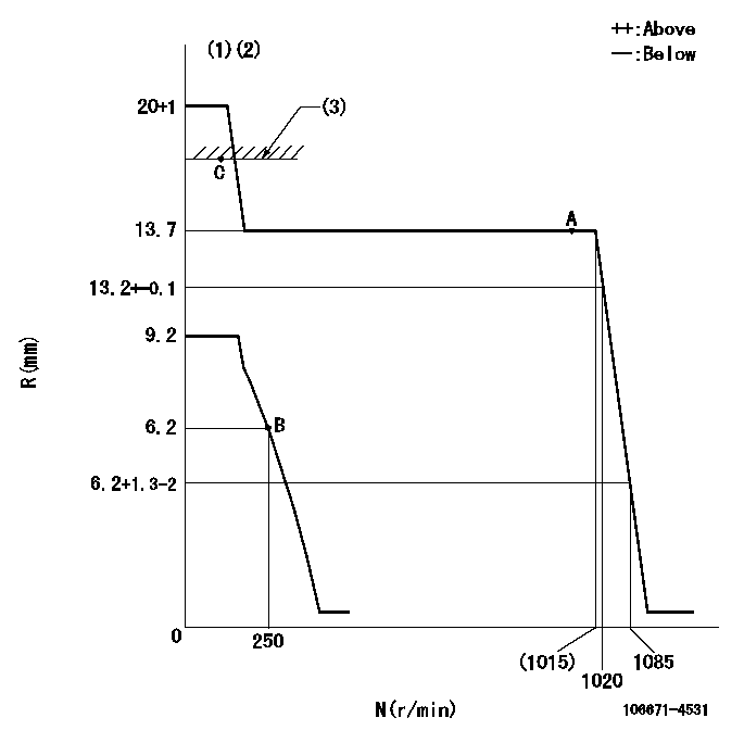
N:Pump speed
R:Rack position (mm)
(1)Target notch: K
(2)Tolerance for racks not indicated: +-0.05mm.
(3)RACK LIMIT
----------
K=23
----------
----------
K=23
----------
Speed control lever angle
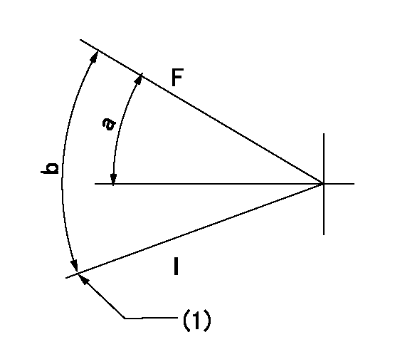
F:Full speed
I:Idle
(1)Stopper bolt setting
----------
----------
a=(31deg)+-5deg b=(31deg)+-5deg
----------
----------
a=(31deg)+-5deg b=(31deg)+-5deg
Stop lever angle
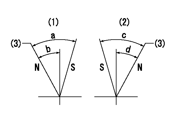
N:Pump normal
S:Stop the pump.
(1)Right front
(2)Right rear
(3)Normal
----------
----------
a=47deg+-5deg b=33deg+-5deg c=53deg+-5deg d=36deg+-5deg
----------
----------
a=47deg+-5deg b=33deg+-5deg c=53deg+-5deg d=36deg+-5deg
Timing setting

(1)Pump vertical direction
(2)Coupling's key groove position for the No. 6 cylinder's beginning of injection
(3)-
(4)-
----------
----------
a=(10deg)
----------
----------
a=(10deg)
Information:
Proper operation and maintenance are key factors in obtaining the maximum life and economy of the engine. Following the directions in this manual will lower operating costs.The time needed for the engine to reach the normal mode of operation is usually less than the time taken for a walk-around-inspection of the engine.After the engine is started and the cold low idle operation is completed, the engine can be operated at rated speed and low power. The engine will reach normal operating temperature faster when operated at rated speed and low power demand than when idled at no load. Typically the engine should be up to operating temperature in a few minutes.Gauges readings should be observed and the data record frequently while the engine is operating. Comparing the data over time will help determine normal readings for each gauge, and help detect abnormal operating developments. Significant changes in the readings should be investigated.Fuel Conservation Practices
The efficiency of your engine can affect the fuel economy. Caterpillar's state-of-the-art design and manufacturing technology provides maximum fuel efficiency in all applications. Follow the recommended operating and maintenance procedures to attain optimum performance for the life of your engine.* Avoid fuel spillage. Fuel expands when warmed, and may overflow from a too-full fuel tank. Inspect fuel lines for leaks, and repair immediately.* Be aware of the heat values of different fuels. Use only recommended fuels.* Avoid unnecessary idling. Shut the engine off rather than idle for long periods of time (unless the temperature is extremely cold).* Observe the air service indicator frequently, and keep the air cleaner elements clean.* Make sure that turbochargers are operating correctly so that the proper air/fuel ratio is maintained. Clean exhaust indicated proper functioning.* Maintain a good electrical system. One bad battery cell will overwork the alternator, consuming excess power and fuel.* Make sure that belts are properly adjusted and in good condition.* Make sure that all air hose connections are tight and do not leak.* Cold engines consume excess fuel. Utilize jacket water and exhaust system heat when possible. Keep radiator fins and water pumps clean and in good repair. Never operate without thermostats. All of these items will help maintain operating temperatures.* Fuel system settings and altitude limits are stamped on the engine Information Plate. If an engine is moved to a higher altitude, settings must be changed by a Caterpillar dealer in order to prevent turbocharger damage and provide maximum engine efficiency. Engines can be operated safely at lower altitudes, but will deliver less horsepower. The fuel settings should be changed by a Caterpillar dealer to obtain the rated horsepower.
The efficiency of your engine can affect the fuel economy. Caterpillar's state-of-the-art design and manufacturing technology provides maximum fuel efficiency in all applications. Follow the recommended operating and maintenance procedures to attain optimum performance for the life of your engine.* Avoid fuel spillage. Fuel expands when warmed, and may overflow from a too-full fuel tank. Inspect fuel lines for leaks, and repair immediately.* Be aware of the heat values of different fuels. Use only recommended fuels.* Avoid unnecessary idling. Shut the engine off rather than idle for long periods of time (unless the temperature is extremely cold).* Observe the air service indicator frequently, and keep the air cleaner elements clean.* Make sure that turbochargers are operating correctly so that the proper air/fuel ratio is maintained. Clean exhaust indicated proper functioning.* Maintain a good electrical system. One bad battery cell will overwork the alternator, consuming excess power and fuel.* Make sure that belts are properly adjusted and in good condition.* Make sure that all air hose connections are tight and do not leak.* Cold engines consume excess fuel. Utilize jacket water and exhaust system heat when possible. Keep radiator fins and water pumps clean and in good repair. Never operate without thermostats. All of these items will help maintain operating temperatures.* Fuel system settings and altitude limits are stamped on the engine Information Plate. If an engine is moved to a higher altitude, settings must be changed by a Caterpillar dealer in order to prevent turbocharger damage and provide maximum engine efficiency. Engines can be operated safely at lower altitudes, but will deliver less horsepower. The fuel settings should be changed by a Caterpillar dealer to obtain the rated horsepower.
Have questions with 106671-4531?
Group cross 106671-4531 ZEXEL
Niigata-Urawa
106671-4531
INJECTION-PUMP ASSEMBLY