Information injection-pump assembly
BOSCH
9 400 619 858
9400619858
ZEXEL
106671-4521
1066714521
MITSUBISHI-HEAV
3626503281
3626503281
Rating:
Service parts 106671-4521 INJECTION-PUMP ASSEMBLY:
1.
_
7.
COUPLING PLATE
8.
_
9.
_
10.
NOZZLE AND HOLDER ASSY
11.
Nozzle and Holder
12.
Open Pre:MPa(Kqf/cm2)
21.6{220}
15.
NOZZLE SET
Include in #1:
106671-4521
as INJECTION-PUMP ASSEMBLY
Cross reference number
BOSCH
9 400 619 858
9400619858
ZEXEL
106671-4521
1066714521
MITSUBISHI-HEAV
3626503281
3626503281
Zexel num
Bosch num
Firm num
Name
Calibration Data:
Adjustment conditions
Test oil
1404 Test oil ISO4113 or {SAEJ967d}
1404 Test oil ISO4113 or {SAEJ967d}
Test oil temperature
degC
40
40
45
Nozzle and nozzle holder
105780-8130
Bosch type code
EFEP215A
Nozzle
105780-0050
Bosch type code
DN6TD119NP1T
Nozzle holder
105780-2090
Bosch type code
EFEP215
Opening pressure
MPa
17.2
Opening pressure
kgf/cm2
175
Injection pipe
Outer diameter - inner diameter - length (mm) mm 8-3-600
Outer diameter - inner diameter - length (mm) mm 8-3-600
Overflow valve
132424-0620
Overflow valve opening pressure
kPa
157
123
191
Overflow valve opening pressure
kgf/cm2
1.6
1.25
1.95
Tester oil delivery pressure
kPa
157
157
157
Tester oil delivery pressure
kgf/cm2
1.6
1.6
1.6
Direction of rotation (viewed from drive side)
Right R
Right R
Injection timing adjustment
Direction of rotation (viewed from drive side)
Right R
Right R
Injection order
1-5-3-6-
2-4
Pre-stroke
mm
3.9
3.85
3.95
Beginning of injection position
Governor side NO.1
Governor side NO.1
Difference between angles 1
Cal 1-5 deg. 60 59.5 60.5
Cal 1-5 deg. 60 59.5 60.5
Difference between angles 2
Cal 1-3 deg. 120 119.5 120.5
Cal 1-3 deg. 120 119.5 120.5
Difference between angles 3
Cal 1-6 deg. 180 179.5 180.5
Cal 1-6 deg. 180 179.5 180.5
Difference between angles 4
Cyl.1-2 deg. 240 239.5 240.5
Cyl.1-2 deg. 240 239.5 240.5
Difference between angles 5
Cal 1-4 deg. 300 299.5 300.5
Cal 1-4 deg. 300 299.5 300.5
Injection quantity adjustment
Adjusting point
A
Rack position
14.8
Pump speed
r/min
1000
1000
1000
Average injection quantity
mm3/st.
197
190
204
Max. variation between cylinders
%
0
-3
3
Basic
*
Fixing the lever
*
Boost pressure
kPa
111
111
Boost pressure
mmHg
835
835
Injection quantity adjustment_02
Adjusting point
D
Rack position
7.3+-0.5
Pump speed
r/min
250
250
250
Average injection quantity
mm3/st.
28
25
31
Max. variation between cylinders
%
0
-10
10
Fixing the rack
*
Boost pressure
kPa
0
0
0
Boost pressure
mmHg
0
0
0
Boost compensator adjustment
Pump speed
r/min
500
500
500
Rack position
(15.1)
Boost pressure
kPa
53.3
50.6
56
Boost pressure
mmHg
400
380
420
Boost compensator adjustment_02
Pump speed
r/min
500
500
500
Rack position
(15.6)
Boost pressure
kPa
98
91.3
104.7
Boost pressure
mmHg
735
685
785
Timer adjustment
Pump speed
r/min
470--
Advance angle
deg.
0
0
0
Remarks
Start
Start
Timer adjustment_02
Pump speed
r/min
420
Advance angle
deg.
0.5
Timer adjustment_03
Pump speed
r/min
720
Advance angle
deg.
4
3.5
4.5
Remarks
Finish
Finish
Test data Ex:
Governor adjustment
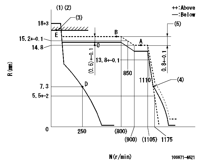
N:Pump speed
R:Rack position (mm)
(1)Notch fixed: K
(2)Tolerance for racks not indicated: +-0.05mm.
(3)RACK LIMIT: RAL
(4)Idle sub spring setting: L1.
(5)Rack difference between N = N1 and N = N2
----------
K=10 RAL=18.9+0.2mm L1=7.3-0.5mm N1=1000r/min N2=750r/min
----------
----------
K=10 RAL=18.9+0.2mm L1=7.3-0.5mm N1=1000r/min N2=750r/min
----------
Speed control lever angle
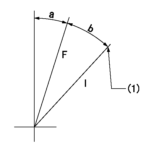
F:Full speed
I:Idle
(1)Stopper bolt setting
----------
----------
a=(0deg)+-5deg b=(33deg)+-5deg
----------
----------
a=(0deg)+-5deg b=(33deg)+-5deg
Stop lever angle
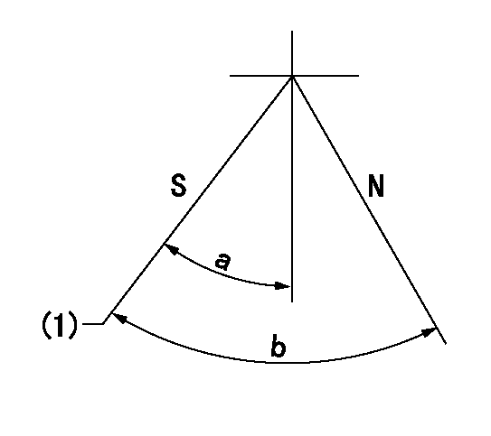
N:Pump normal
S:Stop the pump.
(1)Speed = aa, rack position = bb (sealed at shipping)
----------
aa=0r/min bb=1-0.2mm
----------
a=35deg+-5deg b=70deg+-5deg
----------
aa=0r/min bb=1-0.2mm
----------
a=35deg+-5deg b=70deg+-5deg
Timing setting

(1)Pump vertical direction
(2)Coupling's key groove position at No 1 cylinder's beginning of injection
(3)-
(4)-
----------
----------
a=(100deg)
----------
----------
a=(100deg)
Information:
Gauges provide indications of engine performance. Be sure they are in good working order. You can determine what is the "normal" operating range by observing the gauges over a period of time.Noticeable changes in gauge readings indicate potential gauge or engine problems. This also applies to gauge readings that have changed significantly, but are still within specifications. The cause of any sudden or significant change in gauge readings should be determined and corrected. Contact your Caterpillar dealer for assistance as needed.
Oil Pressure - Indicated engine oil pressure. The oil pressure should be greatest after starting a cold engine. Oil pressure should read between 275 and 606 kPa (40 and 88 psi) when: the engine is running at rated engine speed with SAE 10W30 oil, with an oil temperature no more than 110°C (230°F). A lower pressure is normal at low idling speed.If the oil pressure readings fluctuate after the load has stabilized:1. Remove the load.2. Reduce the engine speed to low idle.3. Check the oil level, and add oil if necessary.The minimum recommended oil pressure at 600 rpm is 103 kPa (15 psi). If low oil pressure or no oil pressure is indicated, stop the engine and determine the cause of the problem. Refer to the Troubleshooting section of the Service Manual, or consult with your Caterpillar dealer.
Engine damage can result if the engine is operated with no oil pressure gauge reading. If no pressure is indicated, stop the engine.
Jacket Water Temperature - Indicates engine coolant temperature. It should normally indicate between 87 to 98°C (189 to 209°F). Higher temperatures may occur under certain conditions. Maximum allowable temperature is 104°C (220°F) with the cooling system pressurized.If the engine is operating with a jacket water temperature above this range:1. Reduce the load and rpm.2. Look for coolant leaks.3. Determine if the engine must be shut down immediately, or if the engine can be cooled by reducing the load.
Ammeter - Indicates the amount of charge or discharge in the battery charging circuit. Normal operation of the indicator should be slightly to the positive (right) side of "0" (zero).Check the charging system for malfunction if, during operation, the indicator is constantly to the negative (left) side of "0" (zero) or shows excessive charge.
Tachometer - Indicates engine rpm (speed). The engine can be operated at high idle without damage, but should not be allowed to overspeed. Overspeeding can seriously damage your engine.
Do not exceed "bare engine high idle" rpm in any situation.
Fuel Level - Indicates fuel level in the fuel tank. The electrically operated fuel level gauge registers only when the START/STOP (ignition key) switch is ON.
Fuel Pressure - Indicates fuel pressure to the injection pump. The indicator should register in the NORMAL (green) range.If the indicator moves to the OUT position or registers below 160 kPa (23 psi) when equipped with a numerical gauge, the engine will not operate properly. In most cases this is caused by a plugged fuel filter.
Service Hour Meter - Indicates the total number of service meter