Information injection-pump assembly
BOSCH
F 019 Z10 520
f019z10520
ZEXEL
106671-4324
1066714324

Rating:
Service parts 106671-4324 INJECTION-PUMP ASSEMBLY:
1.
_
7.
COUPLING PLATE
8.
_
9.
_
10.
NOZZLE AND HOLDER ASSY
11.
Nozzle and Holder
12.
Open Pre:MPa(Kqf/cm2)
13.
NOZZLE-HOLDER
14.
NOZZLE
15.
NOZZLE SET
Include in #1:
106671-4324
as INJECTION-PUMP ASSEMBLY
Cross reference number
BOSCH
F 019 Z10 520
f019z10520
ZEXEL
106671-4324
1066714324
Zexel num
Bosch num
Firm num
Name
Calibration Data:
Adjustment conditions
Test oil
1404 Test oil ISO4113 or {SAEJ967d}
1404 Test oil ISO4113 or {SAEJ967d}
Test oil temperature
degC
40
40
45
Nozzle and nozzle holder
105780-8140
Bosch type code
EF8511/9A
Nozzle
105780-0000
Bosch type code
DN12SD12T
Nozzle holder
105780-2080
Bosch type code
EF8511/9
Opening pressure
MPa
17.2
Opening pressure
kgf/cm2
175
Injection pipe
Outer diameter - inner diameter - length (mm) mm 8-3-600
Outer diameter - inner diameter - length (mm) mm 8-3-600
Overflow valve
131424-4420
Overflow valve opening pressure
kPa
157
123
191
Overflow valve opening pressure
kgf/cm2
1.6
1.25
1.95
Tester oil delivery pressure
kPa
157
157
157
Tester oil delivery pressure
kgf/cm2
1.6
1.6
1.6
Direction of rotation (viewed from drive side)
Right R
Right R
Injection timing adjustment
Direction of rotation (viewed from drive side)
Right R
Right R
Injection order
1-5-3-6-
2-4
Pre-stroke
mm
4.7
4.65
4.75
Beginning of injection position
Drive side NO.1
Drive side NO.1
Difference between angles 1
Cal 1-5 deg. 60 59.5 60.5
Cal 1-5 deg. 60 59.5 60.5
Difference between angles 2
Cal 1-3 deg. 120 119.5 120.5
Cal 1-3 deg. 120 119.5 120.5
Difference between angles 3
Cal 1-6 deg. 180 179.5 180.5
Cal 1-6 deg. 180 179.5 180.5
Difference between angles 4
Cyl.1-2 deg. 240 239.5 240.5
Cyl.1-2 deg. 240 239.5 240.5
Difference between angles 5
Cal 1-4 deg. 300 299.5 300.5
Cal 1-4 deg. 300 299.5 300.5
Injection quantity adjustment
Adjusting point
A
Rack position
10.4
Pump speed
r/min
700
700
700
Average injection quantity
mm3/st.
148
146
150
Max. variation between cylinders
%
0
-2
2
Basic
*
Fixing the lever
*
Boost pressure
kPa
56
56
Boost pressure
mmHg
420
420
Injection quantity adjustment_02
Adjusting point
B
Rack position
11
Pump speed
r/min
1100
1100
1100
Average injection quantity
mm3/st.
154.5
151.5
157.5
Max. variation between cylinders
%
0
-3
3
Fixing the lever
*
Boost pressure
kPa
56
56
Boost pressure
mmHg
420
420
Injection quantity adjustment_03
Adjusting point
H
Rack position
5.2+-0.5
Pump speed
r/min
250
250
250
Average injection quantity
mm3/st.
14.5
13
16
Max. variation between cylinders
%
0
-15
15
Fixing the rack
*
Boost pressure
kPa
0
0
0
Boost pressure
mmHg
0
0
0
Injection quantity adjustment_04
Adjusting point
I
Rack position
-
Pump speed
r/min
100
100
100
Average injection quantity
mm3/st.
165
160
170
Fixing the lever
*
Boost pressure
kPa
56
56
Boost pressure
mmHg
420
420
Rack limit
*
Boost compensator adjustment
Pump speed
r/min
500
500
500
Rack position
8.7
Boost pressure
kPa
22.7
20.7
24.7
Boost pressure
mmHg
170
155
185
Boost compensator adjustment_02
Pump speed
r/min
500
500
500
Rack position
10.4
Boost pressure
kPa
42.7
42.7
42.7
Boost pressure
mmHg
320
320
320
Timer adjustment
Pump speed
r/min
750--
Advance angle
deg.
0
0
0
Remarks
Start
Start
Timer adjustment_02
Pump speed
r/min
700
Advance angle
deg.
0.5
Timer adjustment_03
Pump speed
r/min
1100
Advance angle
deg.
3
2.5
3.5
Remarks
Finish
Finish
Test data Ex:
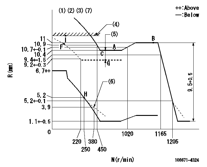
Governor adjustment

N:Pump speed
R:Rack position (mm)
(1)Lever ratio: RT
(2)Target shim dimension: TH
(3)Tolerance for racks not indicated: +-0.05mm.
(4)RACK LIMIT
(5)Boost compensator stroke: BCL
(6)Damper spring setting
(7)Microswitch adjustment unnecessary.
----------
RT=1 TH=2.9mm BCL=1.7+-0.1mm
----------
----------
RT=1 TH=2.9mm BCL=1.7+-0.1mm
----------
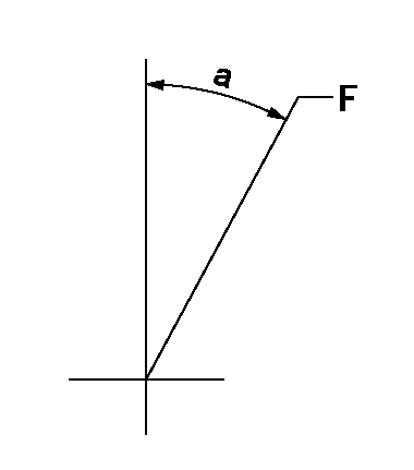
Speed control lever angle

F:Full speed
----------
----------
a=7deg+-5deg
----------
----------
a=7deg+-5deg
0000000901

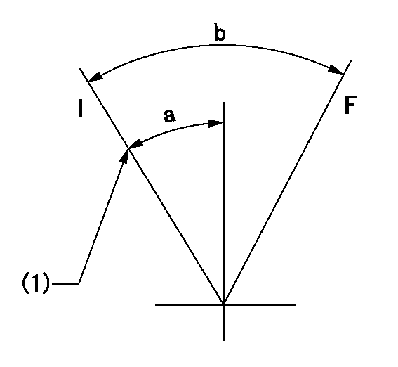
F:Full load
I:Idle
(1)Stopper bolt setting
----------
----------
a=10deg+-5deg b=34deg+-3deg
----------
----------
a=10deg+-5deg b=34deg+-3deg
Stop lever angle

N:Pump normal
S:Stop the pump.
----------
----------
a=40deg+-5deg b=73deg+-5deg
----------
----------
a=40deg+-5deg b=73deg+-5deg
Timing setting

(1)Pump vertical direction
(2)Coupling's key groove position for the No. 6 cylinder's beginning of injection
(3)-
(4)-
----------
----------
a=(70deg)
----------
----------
a=(70deg)
Information:
Distillate Diesel Fuel
Diesel fuels that meet the specifications in the chart below will provide rated engine performance and full component service life. In North America, diesel fuel identified as No. 1-D and No.2-D in ASTM D975 generally meet these specifications. This chart is for diesel fuels that are distilled from crude oil. Diesel fuels from other sources could exhibit detrimental properties that are not defined or controlled by this specification.. There are many other diesel fuel specifications published by governments and technical societies. Those diesel fuel specifications usually do not contain all of the parameters addressed by Caterpillar in this specification. To assure optimum engine performance, a complete fuel analysis should be obtained prior to engine operation. The fuel analysis should include all of the properties listed in the Distillate Fuel Recommendations chart. If a particular fuel does not meet the minimum Caterpillar requirements, the engine could exhibit excessive fuel system wear, fuel system failure, or excessive engine wear caused by deposits or corrosion.0.05 Percent Sulfur Diesel Fuel
In the U.S.A., 0.05 percent sulfur diesel fuel has been used in all on-highway diesel truck engines since January 1, 1994. This low sulfur fuel was mandated as a means of directly reducing particulate emissions from diesel truck engines. This low sulfur fuel will also be used in Caterpillar commercial diesel engines where low emissions are required and where supply sources provide this type of fuel. Caterpillar has not seen any detrimental effects with 0.05 percent sulfur fuel in Caterpillar commercial diesel engines.
Heavy Fuel Oil (HFO), Residual fuel, or Blended fuel must NOT be used in Caterpillar diesel engines (except in certain 3600 Series HFO engines). Severe component wear and component failures will result if HFO type fuels are used.