Information injection-pump assembly
ZEXEL
106671-4300
1066714300
MITSUBISHI-HEAV
3256562060
3256562060

Rating:
Cross reference number
ZEXEL
106671-4300
1066714300
MITSUBISHI-HEAV
3256562060
3256562060
Zexel num
Bosch num
Firm num
Name
Calibration Data:
Adjustment conditions
Test oil
1404 Test oil ISO4113 or {SAEJ967d}
1404 Test oil ISO4113 or {SAEJ967d}
Test oil temperature
degC
40
40
45
Nozzle and nozzle holder
105780-8130
Bosch type code
EFEP215A
Nozzle
105780-0050
Bosch type code
DN6TD119NP1T
Nozzle holder
105780-2090
Bosch type code
EFEP215
Opening pressure
MPa
17.2
Opening pressure
kgf/cm2
175
Injection pipe
Outer diameter - inner diameter - length (mm) mm 8-3-600
Outer diameter - inner diameter - length (mm) mm 8-3-600
Overflow valve opening pressure
kPa
157
123
191
Overflow valve opening pressure
kgf/cm2
1.6
1.25
1.95
Tester oil delivery pressure
kPa
157
157
157
Tester oil delivery pressure
kgf/cm2
1.6
1.6
1.6
Direction of rotation (viewed from drive side)
Left L
Left L
Injection timing adjustment
Direction of rotation (viewed from drive side)
Left L
Left L
Injection order
1-5-3-6-
2-4
Pre-stroke
mm
3.9
3.85
3.95
Rack position
Point B R=B
Point B R=B
Beginning of injection position
Governor side NO.1
Governor side NO.1
Difference between angles 1
Cal 1-5 deg. 60 59.5 60.5
Cal 1-5 deg. 60 59.5 60.5
Difference between angles 2
Cal 1-3 deg. 120 119.5 120.5
Cal 1-3 deg. 120 119.5 120.5
Difference between angles 3
Cal 1-6 deg. 180 179.5 180.5
Cal 1-6 deg. 180 179.5 180.5
Difference between angles 4
Cyl.1-2 deg. 240 239.5 240.5
Cyl.1-2 deg. 240 239.5 240.5
Difference between angles 5
Cal 1-4 deg. 300 299.5 300.5
Cal 1-4 deg. 300 299.5 300.5
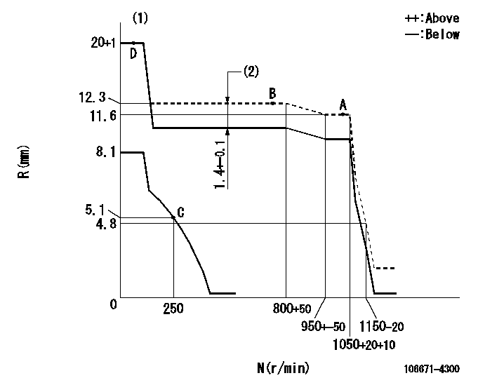
Injection quantity adjustment
Adjusting point
A
Rack position
11.6
Pump speed
r/min
1000
1000
1000
Average injection quantity
mm3/st.
306.2
296.2
316.2
Max. variation between cylinders
%
0
-5
5
Fixing the lever
*
Boost pressure
kPa
140
140
Boost pressure
mmHg
1050
1050
Injection quantity adjustment_02
Adjusting point
B
Rack position
12.3
Pump speed
r/min
750
750
750
Average injection quantity
mm3/st.
308.8
299.8
317.8
Max. variation between cylinders
%
0
-3
3
Basic
*
Fixing the lever
*
Boost pressure
kPa
140
140
Boost pressure
mmHg
1050
1050
Injection quantity adjustment_03
Adjusting point
C
Rack position
5.1+-0.5
Pump speed
r/min
250
250
250
Average injection quantity
mm3/st.
28.5
25.5
31.5
Max. variation between cylinders
%
0
-10
10
Fixing the rack
*
Boost pressure
kPa
0
0
0
Boost pressure
mmHg
0
0
0
Remarks
Injection only at cylinders 1, 3, 4 and 6.
Injection only at cylinders 1, 3, 4 and 6.
Injection quantity adjustment_04
Adjusting point
C
Rack position
5.1
Pump speed
r/min
250
250
250
Average injection quantity
mm3/st.
0
0
5
Fixing the rack
*
Boost pressure
kPa
0
0
0
Boost pressure
mmHg
0
0
0
Remarks
Injection only at cylinders 2 and 5.
Injection only at cylinders 2 and 5.
Boost compensator adjustment
Pump speed
r/min
500
500
500
Rack position
10.9
Boost pressure
kPa
74.6
71.9
77.3
Boost pressure
mmHg
560
540
580
Boost compensator adjustment_02
Pump speed
r/min
500
500
500
Rack position
12.3
Boost pressure
kPa
127
120.3
133.7
Boost pressure
mmHg
950
900
1000
Timer adjustment
Pump speed
r/min
450--
Advance angle
deg.
0
0
0
Remarks
Start
Start
Timer adjustment_02
Pump speed
r/min
400
Advance angle
deg.
0.5
Timer adjustment_03
Pump speed
r/min
700
Advance angle
deg.
1.4
0.9
1.9
Timer adjustment_04
Pump speed
r/min
1050
Advance angle
deg.
4
3.5
4.5
Remarks
Finish
Finish
Test data Ex:
Governor adjustment
N:Pump speed
R:Rack position (mm)
(1)Target notch: K
(2)Boost compensator stroke
----------
K=5
----------
----------
K=5
----------
Speed control lever angle
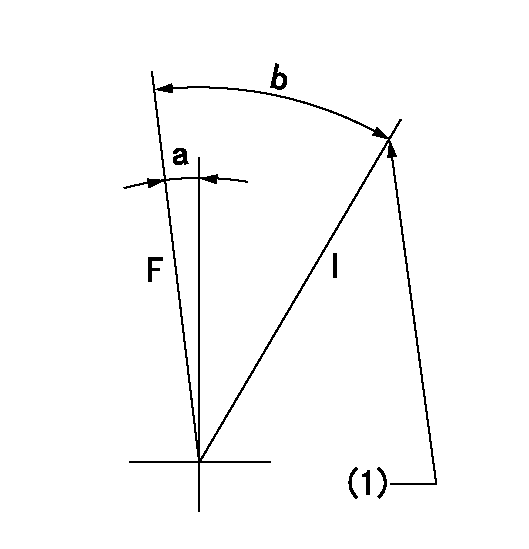
F:Full speed
I:Idle
(1)Stopper bolt setting
----------
----------
a=1deg+-5deg b=27deg+-5deg
----------
----------
a=1deg+-5deg b=27deg+-5deg
Stop lever angle
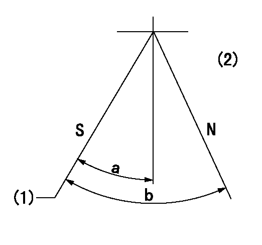
N:Pump normal
S:Stop the pump.
(1)Pump speed aa, rack position bb
(2)Seal after setting the stopper bolt.
----------
aa=0r/min bb=1-0.2mm
----------
a=35deg+-5deg b=70deg+-5deg
----------
aa=0r/min bb=1-0.2mm
----------
a=35deg+-5deg b=70deg+-5deg
Timing setting

(1)Pump vertical direction
(2)Coupling's key groove position at No 1 cylinder's beginning of injection
(3)-
(4)-
----------
----------
a=(20deg)
----------
----------
a=(20deg)
Information:
You must read and understand the warnings and instructions contained in the Safety section of this manual before performing any operation or maintenance procedures.Before proceeding with PM Level 3 maintenance, perform all Daily, PM Level 1 and Level 2 maintenance requirements. The following maintenance procedures are to be performed Every 160 000 km (96,000 miles) or 4000 service hours or 4 years under ideal operating conditions, whichever occurs first.Refer to the Maintenance Schedule and Service Factor chart. Apply the correct Service Factor to determine the proper maintenance interval for your vehicle.Air Compressor
Inspect/Rebuild or Exchange
Do not disconnect the air line from the air compressor governor without purging the air brake and auxiliary air systems.Failure to purge the air brake and auxiliary air systems before removing the air compressor and/or air lines could cause personal injury.
Inspect the air compressor as instructed by the truck/vehicle manufacturers' instructions or for more information on how to check your air compressor, refer to the