Information injection-pump assembly
ZEXEL
106671-4032
1066714032
Rating:
Service parts 106671-4032 INJECTION-PUMP ASSEMBLY:
1.
_
7.
COUPLING PLATE
8.
_
9.
_
11.
Nozzle and Holder
12.
Open Pre:MPa(Kqf/cm2)
25.5(260)
15.
NOZZLE SET
Include in #1:
106671-4032
as INJECTION-PUMP ASSEMBLY
Cross reference number
ZEXEL
106671-4032
1066714032
Zexel num
Bosch num
Firm num
Name
106671-4032
INJECTION-PUMP ASSEMBLY
Calibration Data:
Adjustment conditions
Test oil
1404 Test oil ISO4113 or {SAEJ967d}
1404 Test oil ISO4113 or {SAEJ967d}
Test oil temperature
degC
40
40
45
Nozzle and nozzle holder
105780-8140
Bosch type code
EF8511/9A
Nozzle
105780-0000
Bosch type code
DN12SD12T
Nozzle holder
105780-2080
Bosch type code
EF8511/9
Opening pressure
MPa
17.2
Opening pressure
kgf/cm2
175
Injection pipe
Outer diameter - inner diameter - length (mm) mm 8-3-600
Outer diameter - inner diameter - length (mm) mm 8-3-600
Overflow valve
131425-0120
Overflow valve opening pressure
kPa
157
123
191
Overflow valve opening pressure
kgf/cm2
1.6
1.25
1.95
Tester oil delivery pressure
kPa
157
157
157
Tester oil delivery pressure
kgf/cm2
1.6
1.6
1.6
Direction of rotation (viewed from drive side)
Left L
Left L
Injection timing adjustment
Direction of rotation (viewed from drive side)
Left L
Left L
Injection order
1-4-2-6-
3-5
Pre-stroke
mm
3.9
3.85
3.95
Beginning of injection position
Governor side NO.1
Governor side NO.1
Difference between angles 1
Cal 1-4 deg. 60 59.5 60.5
Cal 1-4 deg. 60 59.5 60.5
Difference between angles 2
Cyl.1-2 deg. 120 119.5 120.5
Cyl.1-2 deg. 120 119.5 120.5
Difference between angles 3
Cal 1-6 deg. 180 179.5 180.5
Cal 1-6 deg. 180 179.5 180.5
Difference between angles 4
Cal 1-3 deg. 240 239.5 240.5
Cal 1-3 deg. 240 239.5 240.5
Difference between angles 5
Cal 1-5 deg. 300 299.5 300.5
Cal 1-5 deg. 300 299.5 300.5
Injection quantity adjustment
Adjusting point
A
Rack position
13.7
Pump speed
r/min
1000
1000
1000
Average injection quantity
mm3/st.
209.3
204.3
214.3
Max. variation between cylinders
%
0
-3
3
Basic
*
Fixing the lever
*
Injection quantity adjustment_02
Adjusting point
B
Rack position
7.1+-0.5
Pump speed
r/min
250
250
250
Average injection quantity
mm3/st.
30
27
33
Max. variation between cylinders
%
0
-10
10
Fixing the rack
*
Remarks
Adjust only variation between cylinders; adjust governor according to governor specifications.
Adjust only variation between cylinders; adjust governor according to governor specifications.
Timer adjustment
Pump speed
r/min
450--
Advance angle
deg.
0
0
0
Remarks
Start
Start
Timer adjustment_02
Pump speed
r/min
400
Advance angle
deg.
0.5
Timer adjustment_03
Pump speed
r/min
720
Advance angle
deg.
4.5
4
5
Remarks
Finish
Finish
Test data Ex:
Governor adjustment
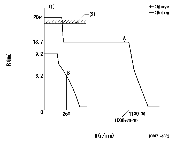
N:Pump speed
R:Rack position (mm)
(1)Target notch: K
(2)RACK LIMIT: RAL
----------
K=20 RAL=16.4+0.2mm
----------
----------
K=20 RAL=16.4+0.2mm
----------
Speed control lever angle
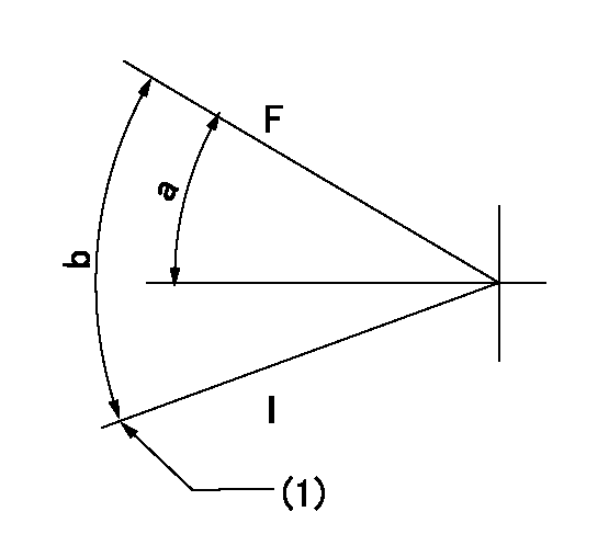
F:Full speed
I:Idle
(1)Stopper bolt setting
----------
----------
a=(32deg)+-5deg b=(32deg)+-5deg
----------
----------
a=(32deg)+-5deg b=(32deg)+-5deg
Stop lever angle

N:Pump normal
S:Stop the pump.
----------
----------
a=36deg+-5deg b=53deg+-5deg
----------
----------
a=36deg+-5deg b=53deg+-5deg
Timing setting

(1)Pump vertical direction
(2)Coupling's key groove position at No 1 cylinder's beginning of injection
(3)-
(4)-
----------
----------
a=(10deg)
----------
----------
a=(10deg)
Information:
Engine Identification
Caterpillar engines are identified with Serial Numbers, Performance Specification Numbers (fuel system settings) and Arrangement Numbers. In some cases Modification Numbers are also used.These numbers are shown on the serial number plate mounted on the engine.Electronic engines have the fuel setting information numbers stored in the personality module and can be read by using Caterpillar service tools (i.e. ECAP or DDT).Caterpillar dealers need all of these numbers to determine which components were included on the engine when it was assembled at the factory. This permits accurate identification of replacement part numbers.Serial Number Plate
Located on the right rear side of the cylinder block.Information Plate
Located on the valve cover.Reference Numbers
Ordering Parts
Quality Caterpillar replacement parts are available from Caterpillar dealers throughout North America and the world. Their parts stocks are up to date and include all parts normally required to protect your investment in Caterpillar engines.* When ordering parts, your order should specify the part number, part name, quantity and serial number, arrangement number and modification number of the engine for which the parts are needed. If in doubt about the part number, please provide your dealer with a complete description of the needed item.* When maintenance or repair is needed for your Caterpillar engine, be prepared to give the dealer all the information that is provided on the Information Plate, described in this manual.* Discuss the problem with the dealer, such as; when it occurs, what happens, etc. This will help the dealer in troubleshooting and solving the problem faster.Fill in blanks for future reference.Chassis Serial No. ____________________Engine Model ____________________Engine Serial No. ____________________Engine Arrangement No. ____________________Modification No. ____________________Engine Low Idle RPM ____________________Engine Full Load RPM ____________________Performance Specification No. ____________________Governor Group No. ____________________Fuel Filter No. ____________________Primary Fuel Filter No. ____________________Lubrication Oil Filter Element No. ____________________Auxiliary Oil Filter Element No. ____________________Supplemental Coolant Additive Maintenance Element No. ____________________Supplemental Coolant Additive Precharge Element No. ____________________Air Cleaner Element No. ____________________Fan Drive Belt Set No. ____________________Alternator Belt No. ____________________Lube System Capacity (Total) ____________________Cooling System Capacity (Total) ____________________
Have questions with 106671-4032?
Group cross 106671-4032 ZEXEL
Niigata-Urawa
106671-4032
INJECTION-PUMP ASSEMBLY