Information injection-pump assembly
ZEXEL
106671-4030
1066714030
NIIGATA-URAWA
W2B47011B
w2b47011b
Rating:
Service parts 106671-4030 INJECTION-PUMP ASSEMBLY:
1.
_
7.
COUPLING PLATE
8.
_
9.
_
11.
Nozzle and Holder
W2C 3231 0A
12.
Open Pre:MPa(Kqf/cm2)
25.5{260}
15.
NOZZLE SET
Include in #1:
106671-4030
as INJECTION-PUMP ASSEMBLY
Cross reference number
ZEXEL
106671-4030
1066714030
NIIGATA-URAWA
W2B47011B
w2b47011b
Zexel num
Bosch num
Firm num
Name
Calibration Data:
Adjustment conditions
Test oil
1404 Test oil ISO4113 or {SAEJ967d}
1404 Test oil ISO4113 or {SAEJ967d}
Test oil temperature
degC
40
40
45
Nozzle and nozzle holder
105780-8140
Bosch type code
EF8511/9A
Nozzle
105780-0000
Bosch type code
DN12SD12T
Nozzle holder
105780-2080
Bosch type code
EF8511/9
Opening pressure
MPa
17.2
Opening pressure
kgf/cm2
175
Injection pipe
Outer diameter - inner diameter - length (mm) mm 8-3-600
Outer diameter - inner diameter - length (mm) mm 8-3-600
Overflow valve
134424-1420
Overflow valve opening pressure
kPa
162
147
177
Overflow valve opening pressure
kgf/cm2
1.65
1.5
1.8
Tester oil delivery pressure
kPa
157
157
157
Tester oil delivery pressure
kgf/cm2
1.6
1.6
1.6
Direction of rotation (viewed from drive side)
Left L
Left L
Injection timing adjustment
Direction of rotation (viewed from drive side)
Left L
Left L
Injection order
1-4-2-6-
3-5
Pre-stroke
mm
3.9
3.85
3.95
Beginning of injection position
Governor side NO.1
Governor side NO.1
Difference between angles 1
Cal 1-4 deg. 60 59.5 60.5
Cal 1-4 deg. 60 59.5 60.5
Difference between angles 2
Cyl.1-2 deg. 120 119.5 120.5
Cyl.1-2 deg. 120 119.5 120.5
Difference between angles 3
Cal 1-6 deg. 180 179.5 180.5
Cal 1-6 deg. 180 179.5 180.5
Difference between angles 4
Cal 1-3 deg. 240 239.5 240.5
Cal 1-3 deg. 240 239.5 240.5
Difference between angles 5
Cal 1-5 deg. 300 299.5 300.5
Cal 1-5 deg. 300 299.5 300.5
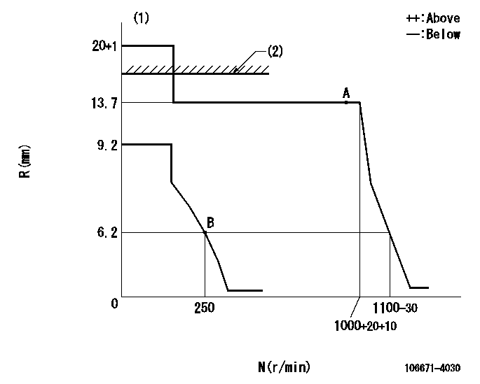
Injection quantity adjustment
Adjusting point
A
Rack position
13.7
Pump speed
r/min
1000
1000
1000
Average injection quantity
mm3/st.
209.3
204.3
214.3
Max. variation between cylinders
%
0
-3
3
Basic
*
Fixing the lever
*
Injection quantity adjustment_02
Adjusting point
B
Rack position
7.1+-0.5
Pump speed
r/min
250
250
250
Average injection quantity
mm3/st.
30
27
33
Max. variation between cylinders
%
0
-10
10
Fixing the rack
*
Remarks
Adjust only variation between cylinders; adjust governor according to governor specifications.
Adjust only variation between cylinders; adjust governor according to governor specifications.
Timer adjustment
Pump speed
r/min
450--
Advance angle
deg.
0
0
0
Remarks
Start
Start
Timer adjustment_02
Pump speed
r/min
400
Advance angle
deg.
0.5
Timer adjustment_03
Pump speed
r/min
720
Advance angle
deg.
4.5
4
5
Remarks
Finish
Finish
Test data Ex:
Governor adjustment
N:Pump speed
R:Rack position (mm)
(1)Target notch: K
(2)RACK LIMIT: RAL
----------
K=20 RAL=16.4+0.2mm
----------
----------
K=20 RAL=16.4+0.2mm
----------
Speed control lever angle
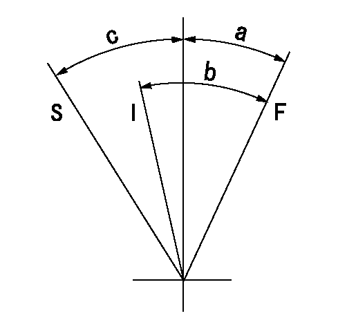
F:Full speed
I:Idle
S:Stop
----------
----------
a=(12deg)+-5deg b=(32deg)+-5deg c=32deg+-3deg
----------
----------
a=(12deg)+-5deg b=(32deg)+-5deg c=32deg+-3deg
Stop lever angle
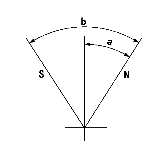
N:Pump normal
S:Stop the pump.
----------
----------
a=42deg+-5deg b=82deg+-5deg
----------
----------
a=42deg+-5deg b=82deg+-5deg
Timing setting

(1)Pump vertical direction
(2)Coupling's key groove position at No 1 cylinder's beginning of injection
(3)-
(4)-
----------
----------
a=(10deg)
----------
----------
a=(10deg)
Information:
Rubber Damper (If Equipped)
The vibration damper can have a visual wobble (movement to the front and rear when in rotation) on the outer ring. This does not mean a replacement is necessary since some wobble of the outer ring is normal. To see if the amount of wobble is acceptable, or replacement is necessary, check the damper with the procedure in the Testing and Adjusting section of the Service Manual.The vibration damper has marks on the hub (1) and ring (2). These marks will indicate the condition of the vibration damper. If the marks are not in alignment, the rubber seal (3) between the ring and the hub has separated from the ring and/or hub. If the marks are not in alignment, install a new vibration damper. Refer to the Service Manual for the necessary replacement procedure.Air Compressor
Inspect/Check
Do not disconnect the air line from the air compressor governor without purging the air brake and auxiliary air systems.Failure to purge the air brake and auxiliary air systems before removing the air compressor could cause personal injury.
Inspect the air compressor as instructed by the OEM truck manufacturers' instructions or for more information on how to check your air compressor, refer to the Service Manual for this engine.If you decide to inspect your air compressor, be sure to observe the following actions. Visually check for fluid leaks and listen for air leaks. Release the air pressure in the air tank until the air pressure is zero. Remove discharge fittings and inspect compressor discharge port and discharge line for excessive carbon deposits. The discharge line must be cleaned or replaced and the compressor checked more thoroughly if there is excessive carbon build-up in either the discharge line or compressor discharge port.For more information on how to check your air compressor, refer to the OEM truck manufacturer's instructions or engine Service Manual.Engine Valve Lash
The procedures for engine valve lash should be performed according to the information in the Service Manual.
Check/Adjust
Be sure the engine cannot be started while this maintenance is being performed. To prevent possible injury, do not use the starting motor to turn the flywheel.Hot engine components can cause burns. Allow additional time for the engine to cool before measuring/adjusting valve lash.
Adjust the valve lash to the setting given in the chart above.Refer to the Service Manual or your Caterpillar dealer for the complete valve adjustment procedure.Bridge Adjustment
The valve bridge should be checked and/or adjusted each time valve lash is checked and/or adjusted. Valve and valve mechanism components do not always wear evenly which can allow the bridge to be out of adjustment.It is not necessary to remove the rocker arm shaft to adjust the valve bridges, but there must be clearance.Engine Valve Rotators
When inspecting the valve rotators, protective glasses or face shield and protective clothing must be worn, to prevent being burned by hot oil or spray.
Observe rotation of valves with engine idling after setting the valve lash. Caterpillar recommends replacement of improperly operating valve rotators. An improperly operating valve rotator