Information injection-pump assembly
BOSCH
9 400 611 138
9400611138
ZEXEL
106671-4020
1066714020
NIIGATA-URAWA
W2B47010B
w2b47010b

Rating:
Cross reference number
BOSCH
9 400 611 138
9400611138
ZEXEL
106671-4020
1066714020
NIIGATA-URAWA
W2B47010B
w2b47010b
Zexel num
Bosch num
Firm num
Name
Calibration Data:
Adjustment conditions
Test oil
1404 Test oil ISO4113 or {SAEJ967d}
1404 Test oil ISO4113 or {SAEJ967d}
Test oil temperature
degC
40
40
45
Nozzle and nozzle holder
105780-8140
Bosch type code
EF8511/9A
Nozzle
105780-0000
Bosch type code
DN12SD12T
Nozzle holder
105780-2080
Bosch type code
EF8511/9
Opening pressure
MPa
17.2
Opening pressure
kgf/cm2
175
Injection pipe
Outer diameter - inner diameter - length (mm) mm 8-3-600
Outer diameter - inner diameter - length (mm) mm 8-3-600
Overflow valve
131425-0120
Overflow valve opening pressure
kPa
157
123
191
Overflow valve opening pressure
kgf/cm2
1.6
1.25
1.95
Tester oil delivery pressure
kPa
157
157
157
Tester oil delivery pressure
kgf/cm2
1.6
1.6
1.6
Direction of rotation (viewed from drive side)
Left L
Left L
Injection timing adjustment
Direction of rotation (viewed from drive side)
Left L
Left L
Injection order
1-4-2-6-
3-5
Pre-stroke
mm
3.9
3.85
3.95
Beginning of injection position
Governor side NO.1
Governor side NO.1
Difference between angles 1
Cal 1-4 deg. 60 59.5 60.5
Cal 1-4 deg. 60 59.5 60.5
Difference between angles 2
Cyl.1-2 deg. 120 119.5 120.5
Cyl.1-2 deg. 120 119.5 120.5
Difference between angles 3
Cal 1-6 deg. 180 179.5 180.5
Cal 1-6 deg. 180 179.5 180.5
Difference between angles 4
Cal 1-3 deg. 240 239.5 240.5
Cal 1-3 deg. 240 239.5 240.5
Difference between angles 5
Cal 1-5 deg. 300 299.5 300.5
Cal 1-5 deg. 300 299.5 300.5
Injection quantity adjustment
Adjusting point
A
Rack position
13.7
Pump speed
r/min
1000
1000
1000
Average injection quantity
mm3/st.
209.3
204.3
214.3
Max. variation between cylinders
%
0
-3
3
Basic
*
Fixing the lever
*
Injection quantity adjustment_02
Adjusting point
B
Rack position
7.1+-0.5
Pump speed
r/min
250
250
250
Average injection quantity
mm3/st.
30
27
33
Max. variation between cylinders
%
0
-10
10
Fixing the rack
*
Remarks
Adjust only variation between cylinders; adjust governor according to governor specifications.
Adjust only variation between cylinders; adjust governor according to governor specifications.
Timer adjustment
Pump speed
r/min
(300)
Advance angle
deg.
0.5
Timer adjustment_02
Pump speed
r/min
600
Advance angle
deg.
2.5
2
3
Timer adjustment_03
Pump speed
r/min
775
Advance angle
deg.
6
5.5
6.5
Remarks
Finish
Finish
Test data Ex:
Governor adjustment
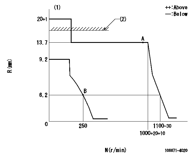
N:Pump speed
R:Rack position (mm)
(1)Target notch: K
(2)RACK LIMIT: RAL
----------
K=20 RAL=16.4+0.2mm
----------
----------
K=20 RAL=16.4+0.2mm
----------
Speed control lever angle
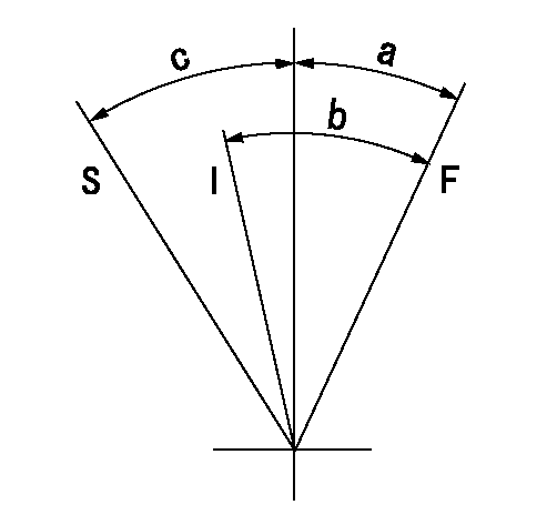
F:Full speed
I:Idle
S:Stop
----------
----------
a=(12deg)+-5deg b=(32deg)+-5deg c=32deg+-3deg
----------
----------
a=(12deg)+-5deg b=(32deg)+-5deg c=32deg+-3deg
Stop lever angle
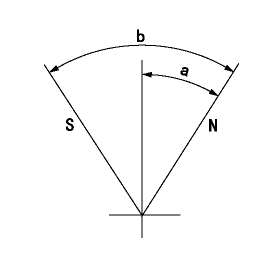
N:Pump normal
S:Stop the pump.
----------
----------
a=42deg+-5deg b=82deg+-5deg
----------
----------
a=42deg+-5deg b=82deg+-5deg
Timing setting

(1)Pump vertical direction
(2)Coupling's key groove position at No 1 cylinder's beginning of injection
(3)-
(4)-
----------
----------
a=(20deg)
----------
----------
a=(20deg)
Information:
Inspect gaskets before assembly and replace if worn or damaged. 10. Install lip-type seal (1) in housing with tooling (A) [Driver Group (1P0510)]. Install the seal with the lip of the seal away from the thermostat. 11. Install thermostat (2) in the housing as shown. 12. Install the new gaskets in position between the regulator manifold and the thermostat housing. Install thermostat housing (3).13. Refill the cooling system with clean water mixed with a 6 to 10 percent concentration of Caterpillar Cooling System Cleaner. Install radiator filler cap. A 9-12 gallon (33-47 L) cooling system capacity requires one gallon (3.8 L) of Caterpillar Cooling System Cleaner to accommodate the 6-10 percent concentration.Caterpillar Cooling System Cleaner is available through your Caterpillar dealer.14. Start and run the engine to circulate fluid in the cooling system for 90 minutes. Stop the engine, remove radiator filler cap and cooling system drain plugs.15. Drain the cleaning solution. Flush the cooling system with clean water until draining water is clear. Clean and install all drain plugs and/or close the drain valve.
Fill the cooling system with the coolant solution at 5 U.S. gal (20 L) per minute or less to avoid air locks.
See Refill Capacities chart in this publication for the capacity of your engine's system.16. Add coolant to the system to bring it to the proper level by mixing a solution of acceptable water, Caterpillar Antifreeze or equivalent. If NOT using Caterpillar Antifreeze, add supplemental coolant additive, or if equipped with a coolant additive element, install the appropriate element.When NOT using Caterpillar Antifreeze, add 1 U.S. quart (1 L) of Caterpillar Coolant Additive (Conditioner) for every 8 U.S. gal (30 L) of cooling system capacity OR change maintenance element only (if equipped).Refer to the Cooling System Specifications in this publication for all information regarding acceptable water, antifreeze and supplemental coolant additive requirements or contact your Caterpillar dealer for assistance.17. Start and run the engine with the filler cap removed. Allow the coolant to warm, the thermostat to open and the coolant level to stabilize.18. Add coolant mixture if necessary to bring the coolant to within 1/2inch (13 mm) below the bottom of the fill tube or the correct level on the sight glass, if equipped.
In cold weather, frequently check the specific gravity of the coolant solution to ensure adequate protection.If the engine is to be stored in, or shipped to an area with freezing temperatures, the cooling system must be either protected to the lowest expected outside temperature or drained completely to prevent damage.Always check your cooling system before operating your engine.
19. Check the condition of the filler cap gasket. If the gasket is damaged, discard the old filler cap and install