Information injection-pump assembly
ZEXEL
106671-3961
1066713961
HINO
220005030A
220005030a

Rating:
Cross reference number
ZEXEL
106671-3961
1066713961
HINO
220005030A
220005030a
Zexel num
Bosch num
Firm num
Name
Calibration Data:
Adjustment conditions
Test oil
1404 Test oil ISO4113 or {SAEJ967d}
1404 Test oil ISO4113 or {SAEJ967d}
Test oil temperature
degC
40
40
45
Nozzle and nozzle holder
105780-8140
Bosch type code
EF8511/9A
Nozzle
105780-0000
Bosch type code
DN12SD12T
Nozzle holder
105780-2080
Bosch type code
EF8511/9
Opening pressure
MPa
17.2
Opening pressure
kgf/cm2
175
Injection pipe
Outer diameter - inner diameter - length (mm) mm 8-3-600
Outer diameter - inner diameter - length (mm) mm 8-3-600
Overflow valve
134424-0920
Overflow valve opening pressure
kPa
162
147
177
Overflow valve opening pressure
kgf/cm2
1.65
1.5
1.8
Tester oil delivery pressure
kPa
157
157
157
Tester oil delivery pressure
kgf/cm2
1.6
1.6
1.6
Direction of rotation (viewed from drive side)
Left L
Left L
Injection timing adjustment
Direction of rotation (viewed from drive side)
Left L
Left L
Injection order
1-4-2-6-
3-5
Pre-stroke
mm
3.3
3.24
3.3
Beginning of injection position
Drive side NO.1
Drive side NO.1
Difference between angles 1
Cal 1-4 deg. 60 59.75 60.25
Cal 1-4 deg. 60 59.75 60.25
Difference between angles 2
Cyl.1-2 deg. 120 119.75 120.25
Cyl.1-2 deg. 120 119.75 120.25
Difference between angles 3
Cal 1-6 deg. 180 179.75 180.25
Cal 1-6 deg. 180 179.75 180.25
Difference between angles 4
Cal 1-3 deg. 240 239.75 240.25
Cal 1-3 deg. 240 239.75 240.25
Difference between angles 5
Cal 1-5 deg. 300 299.75 300.25
Cal 1-5 deg. 300 299.75 300.25
Injection quantity adjustment
Adjusting point
A
Rack position
10.1+-0.
5
Pump speed
r/min
500
500
500
Average injection quantity
mm3/st.
119.5
116.5
122.5
Max. variation between cylinders
%
0
-4
4
Fixing the lever
*
Injection quantity adjustment_02
Adjusting point
B
Rack position
10.5+-0.
5
Pump speed
r/min
700
700
700
Average injection quantity
mm3/st.
129.5
127.5
131.5
Max. variation between cylinders
%
0
-2
2
Basic
*
Fixing the lever
*
Injection quantity adjustment_03
Adjusting point
D
Rack position
11+-0.5
Pump speed
r/min
1150
1150
1150
Average injection quantity
mm3/st.
143
140
146
Max. variation between cylinders
%
0
-4
4
Fixing the lever
*
Injection quantity adjustment_04
Adjusting point
E
Rack position
6.6+-0.5
Pump speed
r/min
225
225
225
Average injection quantity
mm3/st.
15
12
18
Max. variation between cylinders
%
0
-10
10
Fixing the rack
*
Injection quantity adjustment_05
Adjusting point
F
Rack position
11.6+-0.
5
Pump speed
r/min
100
100
100
Average injection quantity
mm3/st.
126.3
119.3
133.3
Fixing the lever
*
Rack limit
*
Timer adjustment
Pump speed
r/min
750--
Advance angle
deg.
0
0
0
Remarks
Start
Start
Timer adjustment_02
Pump speed
r/min
700
Advance angle
deg.
0.5
Timer adjustment_03
Pump speed
r/min
900
Advance angle
deg.
1.4
0.9
1.9
Timer adjustment_04
Pump speed
r/min
1150
Advance angle
deg.
4
3.5
4.5
Remarks
Finish
Finish
Test data Ex:
Governor adjustment
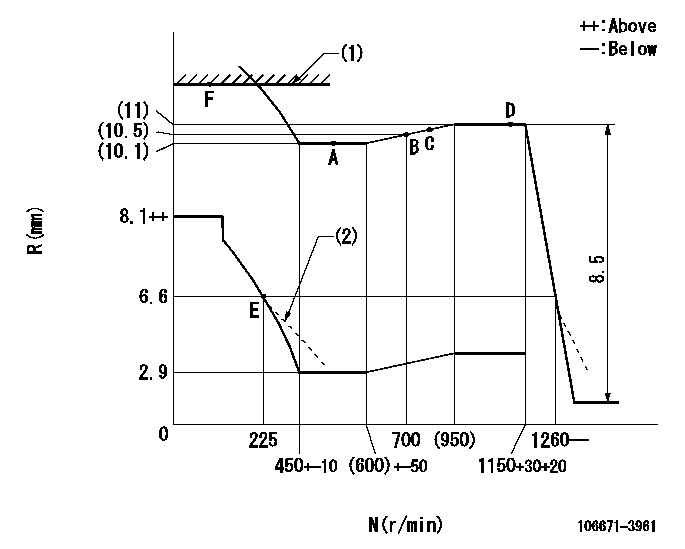
N:Pump speed
R:Rack position (mm)
(1)RACK LIMIT
(2)Damper spring setting: DL
----------
DL=5.8-0.2mm
----------
----------
DL=5.8-0.2mm
----------
Speed control lever angle

F:Full speed
----------
----------
a=3deg+-5deg
----------
----------
a=3deg+-5deg
0000000901
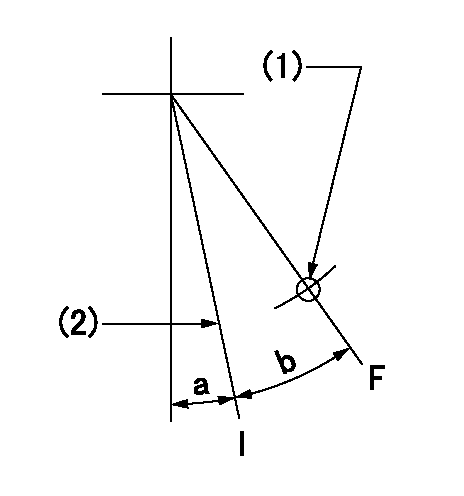
F:Full load
I:Idle
(1)Use the hole at R = aa
(2)Stopper bolt setting
----------
aa=75mm
----------
a=1deg+-5deg b=(28deg)+-3deg
----------
aa=75mm
----------
a=1deg+-5deg b=(28deg)+-3deg
Stop lever angle
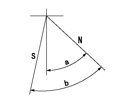
N:Pump normal
S:Stop the pump.
----------
----------
a=40deg+-5deg b=64deg+-5deg
----------
----------
a=40deg+-5deg b=64deg+-5deg
Timing setting

(1)Pump vertical direction
(2)Coupling's key groove position at No 1 cylinder's beginning of injection
(3)-
(4)-
----------
----------
a=(0deg)
----------
----------
a=(0deg)
Information:
Your truck/engine may not have the same or all of the gauges as shown in the illustrations. The illustrations shown are of typical gauges. Gauges provide a "look" inside the engine. Be sure they are in good working order. You can determine what is the "normal" operating range by observing your gauges over a period of time. Noticeable changes in gauge readings are an indication of potential gauge or engine problems. This also applies to gauge readings that have changed significantly but are still within specifications. The cause of any sudden or significant change in the readings should be determined and corrected. Contact your Caterpillar dealer for assistance as needed.
If no oil pressure is indicated, stop the engine. Engine damage can result.
Oil Pressure - Typical oil pressure range is 40 and 88 psi (275 and 606 kPa) (running at rated engine speed, with SAE 10W-30 oil, at operating temperature.) A lower pressure is normal at low idle.The CHECK ENGINE lamp will illuminate (ON) and a diagnostic code will be logged in the Electronic system if oil pressure drops below 5 psi (35 kPa) at low idle rpm. Water Temperature - Typical water temperature range is 175° to 205°F (79° to 98°C). Maximum allowable temperature is 210°F (99°C) with the cooling system pressurized. Somewhat higher temperatures may occur under certain conditions. Ammeter - Indicates the amount of charge or discharge in the battery charging circuit. Typical operation of the indicator should be slightly to the positive (right) side of "0" (zero).
Do not exceed 2300 rpm in any situation or 2100 rpm if equipped with an auxiliary engine brake system.
Tachometer - Indicates engine rpm (speed). The engine can be operated at high idle without damage, but should not be allowed to overspeed. Overspeeding when downshifting, going downhill, etc., can result in serious damage to your engine. Engine Oil Temperature - Indicates engine oil temperature. Maximum oil temperature at rated speed with a full load is 220°F (104°C).The purpose of engine oil is to lubricate bearings and all internal moving parts and to cool the pistons. The oil cooler transfers heat from the oil to the engine jacket water.If the engine cooling system cannot remove the heat from the jacket water, the oil will not be properly cooled. Higher than normal oil temperature indicates a heat problem has occurred in the lubrication and/or cooling system. This can damage the cylinder heads, liners, pistons and crankshaft bearings. Fuel Level - Indicates fuel level in the fuel tank. Electrically operated, it registers only when the key switch is ON. Fuel Pressure - Indicates fuel pressure to the injection pump. The indicator should register in the NORMAL (green) range. Minimum fuel pressure is 23 psi (160 kPa) when equipped with a numerical gauge and the engine is under load. A drop in fuel pressure usually indicates a dirty or plugged fuel filter. Service Hour Meter - Indicates the total number of clock hours the engine has operated.