Information injection-pump assembly
ZEXEL
106671-3940
1066713940
HINO
220004940A
220004940a

Rating:
Cross reference number
ZEXEL
106671-3940
1066713940
HINO
220004940A
220004940a
Zexel num
Bosch num
Firm num
Name
106671-3940
220004940A HINO
INJECTION-PUMP ASSEMBLY
EK100 *
EK100 *
Calibration Data:
Adjustment conditions
Test oil
1404 Test oil ISO4113 or {SAEJ967d}
1404 Test oil ISO4113 or {SAEJ967d}
Test oil temperature
degC
40
40
45
Nozzle and nozzle holder
105780-8140
Bosch type code
EF8511/9A
Nozzle
105780-0000
Bosch type code
DN12SD12T
Nozzle holder
105780-2080
Bosch type code
EF8511/9
Opening pressure
MPa
17.2
Opening pressure
kgf/cm2
175
Injection pipe
Outer diameter - inner diameter - length (mm) mm 8-3-600
Outer diameter - inner diameter - length (mm) mm 8-3-600
Overflow valve
134424-0920
Overflow valve opening pressure
kPa
162
147
177
Overflow valve opening pressure
kgf/cm2
1.65
1.5
1.8
Tester oil delivery pressure
kPa
157
157
157
Tester oil delivery pressure
kgf/cm2
1.6
1.6
1.6
Direction of rotation (viewed from drive side)
Left L
Left L
Injection timing adjustment
Direction of rotation (viewed from drive side)
Left L
Left L
Injection order
1-4-2-6-
3-5
Pre-stroke
mm
4.8
4.74
4.8
Rack position
Point B R=B
Point B R=B
Beginning of injection position
Drive side NO.1
Drive side NO.1
Difference between angles 1
Cal 1-4 deg. 60 59.75 60.25
Cal 1-4 deg. 60 59.75 60.25
Difference between angles 2
Cyl.1-2 deg. 120 119.75 120.25
Cyl.1-2 deg. 120 119.75 120.25
Difference between angles 3
Cal 1-6 deg. 180 179.75 180.25
Cal 1-6 deg. 180 179.75 180.25
Difference between angles 4
Cal 1-3 deg. 240 239.75 240.25
Cal 1-3 deg. 240 239.75 240.25
Difference between angles 5
Cal 1-5 deg. 300 299.75 300.25
Cal 1-5 deg. 300 299.75 300.25
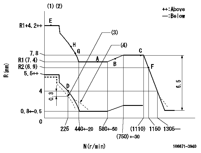
Injection quantity adjustment
Adjusting point
A
Rack position
R1(7.4)
Pump speed
r/min
500
500
500
Average injection quantity
mm3/st.
142
139
145
Max. variation between cylinders
%
0
-4
4
Fixing the lever
*
Injection quantity adjustment_02
Adjusting point
B
Rack position
7.7
Pump speed
r/min
700
700
700
Average injection quantity
mm3/st.
147
145
149
Max. variation between cylinders
%
0
-2
2
Basic
*
Fixing the lever
*
Injection quantity adjustment_03
Adjusting point
C
Rack position
7.8
Pump speed
r/min
1075
1075
1075
Average injection quantity
mm3/st.
151
145
157
Max. variation between cylinders
%
0
-4
4
Fixing the lever
*
Injection quantity adjustment_04
Adjusting point
D
Rack position
4+-0.5
Pump speed
r/min
225
225
225
Average injection quantity
mm3/st.
10
7
13
Max. variation between cylinders
%
0
-15
15
Fixing the rack
*
Test data Ex:
Governor adjustment
N:Pump speed
R:Rack position (mm)
(1)Lever ratio: RT
(2)Target shim dimension: TH
(3)Set to idle at shipping.
(4)Damper spring setting: DL
----------
RT=0.8 TH=2.2mm DL=3.5-0.2mm
----------
----------
RT=0.8 TH=2.2mm DL=3.5-0.2mm
----------
Timer adjustment

(1)Adjusting range
(2)Step response time
(N): Speed of the pump
(L): Load
(theta) Advance angle
(Srd1) Step response time 1
(Srd2) Step response time 2
1. Adjusting conditions for the variable timer
(1)Adjust the clearance between the pickup and the protrusion to L.
----------
L=1-0.2mm N2=800r/min C2=(7deg) t1=2--sec. t2=2--sec.
----------
N1=950+-50r/min P1=0kPa(0kgf/cm2) P2=392kPa(4kgf/cm2) C1=7+-0.3deg R01=0/4 load R02=4/4 load
----------
L=1-0.2mm N2=800r/min C2=(7deg) t1=2--sec. t2=2--sec.
----------
N1=950+-50r/min P1=0kPa(0kgf/cm2) P2=392kPa(4kgf/cm2) C1=7+-0.3deg R01=0/4 load R02=4/4 load
Speed control lever angle

F:Full speed
----------
----------
a=12deg+-5deg
----------
----------
a=12deg+-5deg
0000000901
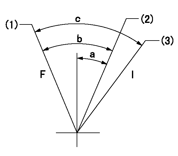
F:Full load
I:Idle
(1)Use the hole at R = aa
(2)Set point D
(3)At shipping
----------
aa=50mm
----------
a=16deg+-5deg b=35deg+-3deg c=36.5deg+-5deg
----------
aa=50mm
----------
a=16deg+-5deg b=35deg+-3deg c=36.5deg+-5deg
Stop lever angle
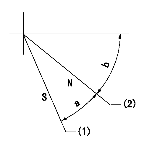
N:Engine manufacturer's normal use
S:Stop the pump.
(1)Rack position = aa
(2)Rack position bb
----------
aa=2mm bb=10mm
----------
a=24deg+-5deg b=55deg+-5deg
----------
aa=2mm bb=10mm
----------
a=24deg+-5deg b=55deg+-5deg
0000001501 RACK SENSOR

(VR) measurement voltage
(I) Part number of the control unit
(G) Apply red paint.
(H): End surface of the pump
1. Rack sensor adjustment (-0620)
(1)Fix the speed control lever at the full position
(2)Set the speed to N1 r/min.
(If the boost compensator is provided, apply boost pressure.)
(3)Adjust the bobbin (A) so that the rack sensor's output voltage is VR+-0.01.
(4)At that time, rack position must be Ra.
(5)Apply G at two places.
Connecting part between the joint (B) and the nut (F)
Connecting part between the joint (B) and the end surface of the pump (H)
----------
N1=900r/min Ra=(7.8)mm
----------
----------
N1=900r/min Ra=(7.8)mm
----------
Timing setting

(1)Pump vertical direction
(2)Coupling's key groove position at No 1 cylinder's beginning of injection
(3)-
(4)-
----------
----------
a=(0deg)
----------
----------
a=(0deg)
Information:
Coolant Water
The minerals (calcium and magnesium) in hard water can combine with cooling system conditioner additives (silicates and phosphates) to drop out of solution and collect inside the radiator.The minerals (silicates, phosphates, calcium and magnesium) can also accumulate onto hot engine surfaces and reduce the effectiveness of the cooling system, especially after a number of heating and cooling cycles. Distilled water is recommended because of less mineral drop out than hard or tap water. Tap water, artificially softened with salt, is not recommended for use in your engine's cooling system. Use water that meets the minimum acceptable water requirement to prevent drop-out of these chemical compounds.To determine your water characteristics, contact the local water department, agricultural agent or an independent laboratory to perform the testing service.Antifreeze
Caterpillar recommends that the coolant mix contain a minimum of 30% Caterpillar Antifreeze, or equivalent and acceptable water to maintain an adequate water pump cavitation temperature for efficient water pump performance.Premix coolant solution to provide protection to the lowest expected outside (ambient) temperature. Pure undiluted antifreeze will freeze at -10°F (-23°C).Only use a greater concentration (above 30%) of Caterpillar Antifreeze as needed for anticipated outside (ambient) temperatures. Do not exceed a coolant mixture of 60% antifreeze to water since a concentration above 60% antifreeze will reduce the engine's freeze protection and increase the possibility of deposit formation in the cooling system.
Use Caterpillar Antifreeze or ASTM D4985-89 (GM Specification 6038-M) Antifreeze. Caterpillar Antifreeze is available through your Caterpillar dealer in quantities that follow. Most commercial antifreezes are formulated for gasoline engine applications and will, therefore, have high silicate content. Caterpillar Antifreeze is formulated with a low silicate content and the proper coolant additives for heavy duty diesel engines.ASTM D4985-89 (GM Specification 6038-M) is a low silicate antifreeze, but supplemental coolant additive must be added. Make proper antifreeze additions.Adding pure antifreeze as a makeup solution for cooling system top-off is an unacceptable practice. It increases the concentration of antifreeze in the cooling system which increases the concentration of dissolved solids and undissolved chemical inhibitors in the cooling system. Add antifreeze mixed with acceptable water to the same freeze protection as your cooling system. Use the chart below to assist in determining the concentration of antifreeze to use. Check the coolant solution frequently in cold weather for glycol concentration with the 5P0957 or 5P3514 Coolant Tester to ensure adequate protection. Both testers are identical except temperature scale. They give immediate, accurate readings and can be used for antifreeze/coolants that contain ethylene or propylene glycol. Both are available at your Caterpillar dealer.If propylene glycol based antifreeze is used, DO NOT allow concentration greater than a 50/50 antifreeze to water mixture. The measurement of freeze protection must be made with a refractive-type tester (5P0957 or 5P3514) rather than a hydrometer-type, which can be used to test ethylene glycol based antifreeze.Supplemental Coolant Additive
Supplemental coolant additive is necessary to prevent rust, scale, pitting and/or corrosion of engine parts that coolant comes in contact with. Most antifreeze solutions DO NOT contain
Have questions with 106671-3940?
Group cross 106671-3940 ZEXEL
Hino
106671-3940
220004940A
INJECTION-PUMP ASSEMBLY
EK100
EK100