Information injection-pump assembly
BOSCH
9 400 613 084
9400613084
ZEXEL
106671-3911
1066713911
HINO
220004651A
220004651a

Rating:
Service parts 106671-3911 INJECTION-PUMP ASSEMBLY:
1.
_
7.
COUPLING PLATE
8.
_
9.
_
11.
Nozzle and Holder
23600-1690
12.
Open Pre:MPa(Kqf/cm2)
14.7{150}/21.6{220}

15.
NOZZLE SET
Include in #1:
106671-3911
as INJECTION-PUMP ASSEMBLY
Cross reference number
BOSCH
9 400 613 084
9400613084
ZEXEL
106671-3911
1066713911
HINO
220004651A
220004651a
Zexel num
Bosch num
Firm num
Name
106671-3911
9 400 613 084
220004651A HINO
INJECTION-PUMP ASSEMBLY
EK100 * K 14CA PE6P,6PD PE
EK100 * K 14CA PE6P,6PD PE
Calibration Data:
Adjustment conditions
Test oil
1404 Test oil ISO4113 or {SAEJ967d}
1404 Test oil ISO4113 or {SAEJ967d}
Test oil temperature
degC
40
40
45
Nozzle and nozzle holder
105780-8140
Bosch type code
EF8511/9A
Nozzle
105780-0000
Bosch type code
DN12SD12T
Nozzle holder
105780-2080
Bosch type code
EF8511/9
Opening pressure
MPa
17.2
Opening pressure
kgf/cm2
175
Injection pipe
Outer diameter - inner diameter - length (mm) mm 8-3-600
Outer diameter - inner diameter - length (mm) mm 8-3-600
Overflow valve
134424-0920
Overflow valve opening pressure
kPa
162
147
177
Overflow valve opening pressure
kgf/cm2
1.65
1.5
1.8
Tester oil delivery pressure
kPa
157
157
157
Tester oil delivery pressure
kgf/cm2
1.6
1.6
1.6
Direction of rotation (viewed from drive side)
Left L
Left L
Injection timing adjustment
Direction of rotation (viewed from drive side)
Left L
Left L
Injection order
1-4-2-6-
3-5
Pre-stroke
mm
4.8
4.74
4.8
Rack position
Point B R=B
Point B R=B
Beginning of injection position
Drive side NO.1
Drive side NO.1
Difference between angles 1
Cal 1-4 deg. 60 59.75 60.25
Cal 1-4 deg. 60 59.75 60.25
Difference between angles 2
Cyl.1-2 deg. 120 119.75 120.25
Cyl.1-2 deg. 120 119.75 120.25
Difference between angles 3
Cal 1-6 deg. 180 179.75 180.25
Cal 1-6 deg. 180 179.75 180.25
Difference between angles 4
Cal 1-3 deg. 240 239.75 240.25
Cal 1-3 deg. 240 239.75 240.25
Difference between angles 5
Cal 1-5 deg. 300 299.75 300.25
Cal 1-5 deg. 300 299.75 300.25
Injection quantity adjustment
Adjusting point
A
Rack position
R1(7.3)
Pump speed
r/min
500
500
500
Average injection quantity
mm3/st.
139
136
142
Max. variation between cylinders
%
0
-4
4
Fixing the lever
*
Injection quantity adjustment_02
Adjusting point
B
Rack position
7.7
Pump speed
r/min
700
700
700
Average injection quantity
mm3/st.
147
145
149
Max. variation between cylinders
%
0
-2
2
Basic
*
Fixing the lever
*
Injection quantity adjustment_03
Adjusting point
C
Rack position
7.8
Pump speed
r/min
1075
1075
1075
Average injection quantity
mm3/st.
151
145
157
Max. variation between cylinders
%
0
-4
4
Fixing the lever
*
Injection quantity adjustment_04
Adjusting point
D
Rack position
4+-0.5
Pump speed
r/min
225
225
225
Average injection quantity
mm3/st.
10
7
13
Max. variation between cylinders
%
0
-15
15
Fixing the rack
*
Test data Ex:
Governor adjustment
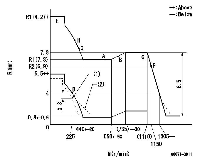
N:Pump speed
R:Rack position (mm)
(1)Set to idle at shipping.
(2)Damper spring setting: DL
----------
DL=3.5-0.2mm
----------
----------
DL=3.5-0.2mm
----------
Timer adjustment

(1)Adjusting range
(2)Step response time
(N): Speed of the pump
(L): Load
(theta) Advance angle
(Srd1) Step response time 1
(Srd2) Step response time 2
1. Adjusting conditions for the variable timer
(1)Adjust the clearance between the pickup and the protrusion to L.
----------
L=1-0.2mm N2=800r/min C2=(7deg) t1=2--sec. t2=2--sec.
----------
N1=950+-50r/min P1=0kPa(0kgf/cm2) P2=392kPa(4kgf/cm2) C1=7+-0.3deg R01=0/4load R02=4/4load
----------
L=1-0.2mm N2=800r/min C2=(7deg) t1=2--sec. t2=2--sec.
----------
N1=950+-50r/min P1=0kPa(0kgf/cm2) P2=392kPa(4kgf/cm2) C1=7+-0.3deg R01=0/4load R02=4/4load
Speed control lever angle

F:Full speed
----------
----------
a=12deg+-5deg
----------
----------
a=12deg+-5deg
0000000901
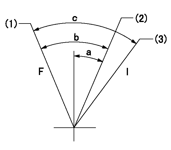
F:Full load
I:Idle
(1)Use the hole at R = aa
(2)Set point D
(3)At shipping
----------
aa=50mm
----------
a=16deg+-5deg b=34deg+-3deg c=35.5deg+-5deg
----------
aa=50mm
----------
a=16deg+-5deg b=34deg+-3deg c=35.5deg+-5deg
Stop lever angle

N:Pump normal
S:Stop the pump.
----------
----------
a=15deg+-5deg b=64deg+-5deg
----------
----------
a=15deg+-5deg b=64deg+-5deg
0000001501 RACK SENSOR

(VR) measurement voltage
(I) Part number of the control unit
(G) Apply red paint.
(H): End surface of the pump
1. Rack sensor adjustment (-0620)
(1)Fix the speed control lever at the full position
(2)Set the speed to N1 r/min.
(If the boost compensator is provided, apply boost pressure.)
(3)Adjust the bobbin (A) so that the rack sensor's output voltage is VR+-0.01.
(4)At that time, rack position must be Ra.
(5)Apply G at two places.
Connecting part between the joint (B) and the nut (F)
Connecting part between the joint (B) and the end surface of the pump (H)
----------
N1=900r/min Ra=(7.8)mm
----------
----------
N1=900r/min Ra=(7.8)mm
----------
Timing setting

(1)Pump vertical direction
(2)Coupling's key groove position at No 1 cylinder's beginning of injection
(3)-
(4)-
----------
----------
a=(0deg)
----------
----------
a=(0deg)
Information:
Operating Cost Information
The term "Life Cycle Costs" can be defined as the sum of the individual costs experienced by an engine from the day of purchase until the day of retirement. In other words, the total Owning and Operating Costs. Owning Costs are fixed costs such as initial purchase price, interest on borrowed money, depreciation and taxes. Operating Costs are a combination of fixed and variable costs such as fuel, oil, operator expenses, equipment maintenance and repair, engine maintenance and repair, and downtime.The difference between revenues generated and Life Cycle Costs (total Owning and Operating Costs) is profit.Caterpillar and your Caterpillar dealer cannot guarantee that you will make a profit. However, Caterpillar and your Caterpillar dealer can provide you with a variety of services that can help you reduce the costs that impact your profits.An Engine Operating Cost Analysis is a service provided by your dealer that was developed by Caterpillar to help you reduce the Life Cycle Cost of your engine. More specifically, an Engine Operating Cost Analysis is a computerized program that examines current and prospective oil, fuel, maintenance, minor repair, overhaul and downtime costs for the period of time you expect to own the engine. It also calculates the operating cost per hour.This useful tool provides your dealer with the specific information needed to develop a customized Maintenance Management program for your operation which will minimize your engine's operating costs.Before a cost analysis can be performed, your dealer needs to gather as much information as possible about your operation. He will need to know the length of time you plan to keep your engine, your average cost of fuel and oil as well as a variety of other ownership and cost related facts and figures.Once this information is obtained, your dealer will enter the data into an established computerized program to produce an Engine Operating Cost Analysis printout reflecting your current and projected operating costs per hour. Current and expected cost information is reflected in the data provided by you. These are the costs that affect your engine's operating cost.The General Information section contains basic user data such as name, business, location, ownership, usage per year, etc., information.The Engine Operating Information section is divided into eight subsections that address fuel consumption, oil consumption, preventive maintenance, component repairs such as water pumps, turbochargers, air compressors, etc., before failure repairs, after failure repairs, user's revenue rate per hour and lastly, miscellaneous costs such as operator wages, insurance premiums, etc.Engine Operating Cost Summary
The Operating Cost Summary is exactly what it implies, a summary. Here the total dollar expense and percentage of the total operating expense is calculated for each subsection. The individual elements are then totaled and divided by the ownership period to yield the cost per hour. Similar calculations are also made for only the maintenance and repair portion of the total operating cost.An Engine Operating Cost Analysis is a useful tool that can be used to: * Project the expected operating cost of a Caterpillar engine.*
Have questions with 106671-3911?
Group cross 106671-3911 ZEXEL
Hino
106671-3911
9 400 613 084
220004651A
INJECTION-PUMP ASSEMBLY
EK100
EK100