Information injection-pump assembly
BOSCH
9 400 616 784
9400616784
ZEXEL
106671-3900
1066713900
HINO
220004820A
220004820a

Rating:
Service parts 106671-3900 INJECTION-PUMP ASSEMBLY:
1.
_
7.
COUPLING PLATE
8.
_
9.
_
11.
Nozzle and Holder
236001621B
12.
Open Pre:MPa(Kqf/cm2)
14.7{150}/21.6{220}

15.
NOZZLE SET
Include in #1:
106671-3900
as INJECTION-PUMP ASSEMBLY
Cross reference number
BOSCH
9 400 616 784
9400616784
ZEXEL
106671-3900
1066713900
HINO
220004820A
220004820a
Zexel num
Bosch num
Firm num
Name
106671-3900
9 400 616 784
220004820A HINO
INJECTION-PUMP ASSEMBLY
EK100 * K
EK100 * K
Calibration Data:
Adjustment conditions
Test oil
1404 Test oil ISO4113 or {SAEJ967d}
1404 Test oil ISO4113 or {SAEJ967d}
Test oil temperature
degC
40
40
45
Nozzle and nozzle holder
105780-8140
Bosch type code
EF8511/9A
Nozzle
105780-0000
Bosch type code
DN12SD12T
Nozzle holder
105780-2080
Bosch type code
EF8511/9
Opening pressure
MPa
17.2
Opening pressure
kgf/cm2
175
Injection pipe
Outer diameter - inner diameter - length (mm) mm 8-3-600
Outer diameter - inner diameter - length (mm) mm 8-3-600
Overflow valve
134424-0920
Overflow valve opening pressure
kPa
162
147
177
Overflow valve opening pressure
kgf/cm2
1.65
1.5
1.8
Tester oil delivery pressure
kPa
157
157
157
Tester oil delivery pressure
kgf/cm2
1.6
1.6
1.6
Direction of rotation (viewed from drive side)
Left L
Left L
Injection timing adjustment
Direction of rotation (viewed from drive side)
Left L
Left L
Injection order
1-4-2-6-
3-5
Pre-stroke
mm
4.8
4.74
4.8
Beginning of injection position
Drive side NO.1
Drive side NO.1
Difference between angles 1
Cal 1-4 deg. 60 59.75 60.25
Cal 1-4 deg. 60 59.75 60.25
Difference between angles 2
Cyl.1-2 deg. 120 119.75 120.25
Cyl.1-2 deg. 120 119.75 120.25
Difference between angles 3
Cal 1-6 deg. 180 179.75 180.25
Cal 1-6 deg. 180 179.75 180.25
Difference between angles 4
Cal 1-3 deg. 240 239.75 240.25
Cal 1-3 deg. 240 239.75 240.25
Difference between angles 5
Cal 1-5 deg. 300 299.75 300.25
Cal 1-5 deg. 300 299.75 300.25
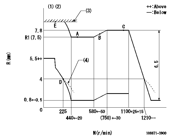
Injection quantity adjustment
Adjusting point
A
Rack position
R1(7.5)
Pump speed
r/min
500
500
500
Average injection quantity
mm3/st.
145
142
148
Max. variation between cylinders
%
0
-4
4
Fixing the lever
*
Injection quantity adjustment_02
Adjusting point
B
Rack position
7.7
Pump speed
r/min
700
700
700
Average injection quantity
mm3/st.
147
145
149
Max. variation between cylinders
%
0
-2
2
Basic
*
Fixing the lever
*
Injection quantity adjustment_03
Adjusting point
C
Rack position
7.8
Pump speed
r/min
1075
1075
1075
Average injection quantity
mm3/st.
151
145
157
Max. variation between cylinders
%
0
-4
4
Fixing the lever
*
Injection quantity adjustment_04
Adjusting point
D
Rack position
4+-0.5
Pump speed
r/min
225
225
225
Average injection quantity
mm3/st.
10
7
13
Max. variation between cylinders
%
0
-15
15
Fixing the rack
*
Injection quantity adjustment_05
Adjusting point
E
Rack position
9+-0.5
Pump speed
r/min
100
100
100
Average injection quantity
mm3/st.
158
153
163
Fixing the lever
*
Rack limit
*
Timer adjustment
Pump speed
r/min
(865)
Advance angle
deg.
0
0
0
Remarks
Start
Start
Timer adjustment_02
Pump speed
r/min
1075
Advance angle
deg.
4.5
4.2
4.8
Remarks
Finish
Finish
Test data Ex:
Governor adjustment
N:Pump speed
R:Rack position (mm)
(1)Lever ratio: RT
(2)Target shim dimension: TH
(3)RACK LIMIT: RAL
(4)Damper spring setting: DL
----------
RT=0.8 TH=2.7mm RAL=(9)mm DL=3.5-0.2mm
----------
----------
RT=0.8 TH=2.7mm RAL=(9)mm DL=3.5-0.2mm
----------
Speed control lever angle

F:Full speed
----------
----------
a=3deg+-5deg
----------
----------
a=3deg+-5deg
0000000901
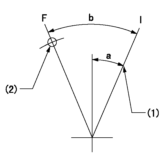
F:Full load
I:Idle
(1)Stopper bolt setting
(2)Use the hole at R = aa
----------
aa=50mm
----------
a=16deg+-5deg b=36deg+-3deg
----------
aa=50mm
----------
a=16deg+-5deg b=36deg+-3deg
Stop lever angle

N:Pump normal
S:Stop the pump.
----------
----------
a=15deg+-5deg b=64deg+-5deg
----------
----------
a=15deg+-5deg b=64deg+-5deg
0000001501 RACK SENSOR

(VR) measurement voltage
(I) Part number of the control unit
(G) Apply red paint.
(H): End surface of the pump
1. Rack limit adjustment
(1)Mount the joint (B).
(2)Select the shim (D) so that the rack limit's rack position is obtained at that time.
(3)Install the rod (E) to the block (C).
The distance between the pump end face and the rod (E) at rack limit must be L.
2. Rack sensor adjustment (-0020)
(1)Screw in the bobbin (A) until it contacts the joint (B).
(2)Fix the speed control lever at the full side.
(3)Set at speed N.
(4)Adjust the depth that the bobbin (A) is screwed in so that the control unit's rack sensor output voltage is VR+-0.01 (V), then tighten the nut (F). (If equipped with a boost compensator, perform with boost pressure applied.)
(5)Adjust the bobbin (A) so that the rack sensor's output voltage is VR+-0.01.
(6)Apply G at two places.
Connecting part between the joint (B) and the nut (F)
Connecting part between the joint (B) and the end surface of the pump (H)
----------
L=38-0.2mm N=900r/min Ra=(7.8)mm
----------
----------
L=38-0.2mm N=900r/min Ra=(7.8)mm
----------
Timing setting

(1)Pump vertical direction
(2)Coupling's key groove position at No 1 cylinder's beginning of injection
(3)-
(4)-
----------
----------
a=(0deg)
----------
----------
a=(0deg)
Information:
Refer to the topics in the Operation & Maintenance Manual, SEBU6150, SR4 Generators and Control Panels, and the Maintenance Schedules in this manual for page numbers and information to perform the maintenance specified in the following schedules.Weekly (Before Starting Engine)
Walk-Around Inspection - Inspect engine for leaks and loose connections Engine Crankcase - Check oil level Cooling System - Check coolant level Battery Charger - Check for proper operation Batteries - Clean/Check electrolyte level Air Starter System (if equipped) - Check lubricator oil level, air pressure and drain condensation Engine Air Cleaner - Check service indicator Block Heater - Check for proper operation, maintain 32°C (90°F) temperature Aftercooler - Inspect ATAAC Belts - Inspect/Replace Engine Protection Devices - Inspect system and gauges for proper operation Generator and Control Panel - Inspect componentsWeekly (With Engine Running)*
Walk-Around Inspection - Inspect engine for leaks and loose connections and generator louvers for proper operation Engine Crankcase - Check oil level Oil Pressure - Check gauge reading Generator - Check frequency (rpm) and generated voltageWeekly (After Stopping Engine)*
Walk-Around Inspection - Inspect engine and report malfunction and make necessary repairs Automatic Switches - Check for proper position to execute auto-start Battery Charger - Record charging amperage readingYearly (Before Starting Engine)*
Cooling System - Check coolant level, Test for concentration of supplemental coolant additive Crankcase Breather - Clean Valve Lash - Check/Adjust Governor - Inspect for leaks Governor Linkage - Check/Adjust and Lubricate Air Inlet Piping - Inspect Engine Air Cleaner - Check service indicator, Replace element if necessary Generator - Lubricate bearingYearly (With Engine Running)*
Engine Protection Devices - Inspect system and gauges for proper operation;/bs/, Record gauge readings Radiator (If Equipped) - Inspect for leaks and loose connections and louvers for proper operation Load Test - Operate the engine at a minimum of 30 percent of rated load for minimum of two hours Engine Mounts - InspectYearly (After Stopping Engine)*
Scheduled Oil Sampling (S O S) Analysis - Obtain Engine Oil and Filters - ReplaceEvery Three Years (Before Starting Engine)*
Turbocharger - Inspect/Check bearing end play and radial clearance Governor - Inspect for leaks Thermostat - Replace Coolant Hoses - Replace Cooling System - Clean/Flush coolant Batteries - ReplaceEvery Three Years (With Engine Running)*
Walk-Around Inspection - Inspect engine for leaks and loose connections Engine Protection Devices - Inspect system and gauges for proper operation, Record gauge readings Engine Crankcase - Check oil level Radiator (If Equipped) - Inspect for leaks and loose connections and louvers for proper operation Load Test - Operate at a minimum of 30 percent of rated load for minimum of two hours Exhaust System - Check for leaksEvery Three Years (After Stopping Engine)*
Walk-Around Inspection - Inspect engine and report malfunction and make necessary repairs Scheduled Oil Sampling (S O S) Analysis - Obtain Engine Oil and Filters - Replace Battery Charger - Record charging amp reading Automatic Switches - Check for proper position to execute auto-start Coolant Analysis - ObtainEvery Four Years
Drain/Replace Engine Coolant (Extended Life Coolant Only)*First Perform Previous Maintenance Items
Have questions with 106671-3900?
Group cross 106671-3900 ZEXEL
Hino
106671-3900
9 400 616 784
220004820A
INJECTION-PUMP ASSEMBLY
EK100
EK100