Information injection-pump assembly
ZEXEL
106671-3820
1066713820
HINO
220004520A
220004520a
Rating:
Cross reference number
ZEXEL
106671-3820
1066713820
HINO
220004520A
220004520a
Zexel num
Bosch num
Firm num
Name
Calibration Data:
Adjustment conditions
Test oil
1404 Test oil ISO4113 or {SAEJ967d}
1404 Test oil ISO4113 or {SAEJ967d}
Test oil temperature
degC
40
40
45
Nozzle and nozzle holder
105780-8140
Bosch type code
EF8511/9A
Nozzle
105780-0000
Bosch type code
DN12SD12T
Nozzle holder
105780-2080
Bosch type code
EF8511/9
Opening pressure
MPa
17.2
Opening pressure
kgf/cm2
175
Injection pipe
Outer diameter - inner diameter - length (mm) mm 8-3-600
Outer diameter - inner diameter - length (mm) mm 8-3-600
Overflow valve
134424-0920
Overflow valve opening pressure
kPa
177
143
211
Overflow valve opening pressure
kgf/cm2
1.8
1.45
2.15
Tester oil delivery pressure
kPa
157
157
157
Tester oil delivery pressure
kgf/cm2
1.6
1.6
1.6
Direction of rotation (viewed from drive side)
Left L
Left L
Injection timing adjustment
Direction of rotation (viewed from drive side)
Left L
Left L
Injection order
1-4-2-6-
3-5
Pre-stroke
mm
3.3
3.24
3.3
Beginning of injection position
Drive side NO.1
Drive side NO.1
Difference between angles 1
Cal 1-4 deg. 60 59.75 60.25
Cal 1-4 deg. 60 59.75 60.25
Difference between angles 2
Cyl.1-2 deg. 120 119.75 120.25
Cyl.1-2 deg. 120 119.75 120.25
Difference between angles 3
Cal 1-6 deg. 180 179.75 180.25
Cal 1-6 deg. 180 179.75 180.25
Difference between angles 4
Cal 1-3 deg. 240 239.75 240.25
Cal 1-3 deg. 240 239.75 240.25
Difference between angles 5
Cal 1-5 deg. 300 299.75 300.25
Cal 1-5 deg. 300 299.75 300.25
Injection quantity adjustment
Adjusting point
-
Rack position
11+-0.5
Pump speed
r/min
700
700
700
Average injection quantity
mm3/st.
144
142
146
Max. variation between cylinders
%
0
-2
2
Basic
*
Fixing the rack
*
Standard for adjustment of the maximum variation between cylinders
*
Injection quantity adjustment_02
Adjusting point
H
Rack position
7+-0.5
Pump speed
r/min
225
225
225
Average injection quantity
mm3/st.
15
12
18
Max. variation between cylinders
%
0
-15
15
Fixing the rack
*
Standard for adjustment of the maximum variation between cylinders
*
Injection quantity adjustment_03
Adjusting point
A
Rack position
R1(11.1)
Pump speed
r/min
700
700
700
Average injection quantity
mm3/st.
144
142
146
Basic
*
Fixing the lever
*
Injection quantity adjustment_04
Adjusting point
B
Rack position
R1+0.6
Pump speed
r/min
1150
1150
1150
Average injection quantity
mm3/st.
154
148
160
Fixing the lever
*
Injection quantity adjustment_05
Adjusting point
C
Rack position
R1-0.3
Pump speed
r/min
500
500
500
Average injection quantity
mm3/st.
132
126
138
Fixing the lever
*
Injection quantity adjustment_06
Adjusting point
I
Rack position
R2
Pump speed
r/min
100
100
100
Average injection quantity
mm3/st.
126.3
119.3
133.3
Fixing the lever
*
Rack limit
*
Timer adjustment
Pump speed
r/min
1000--
Advance angle
deg.
0
0
0
Remarks
Start
Start
Timer adjustment_02
Pump speed
r/min
950
Advance angle
deg.
0.5
Timer adjustment_03
Pump speed
r/min
1000
Advance angle
deg.
1.5
Timer adjustment_04
Pump speed
r/min
1050
Advance angle
deg.
1.9
1.4
2.4
Timer adjustment_05
Pump speed
r/min
1150
Advance angle
deg.
4.5
4.2
4.8
Remarks
Finish
Finish
Test data Ex:
Governor adjustment
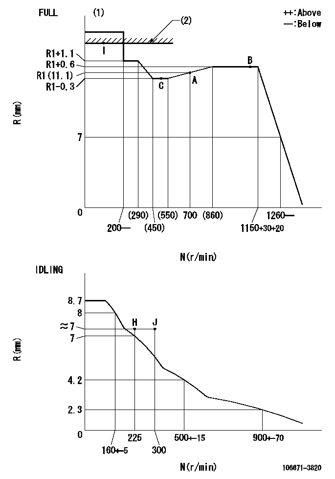
N:Pump speed
R:Rack position (mm)
(1)Torque cam stamping: T1
(2)RACK LIMIT
----------
T1=B06
----------
----------
T1=B06
----------
Speed control lever angle
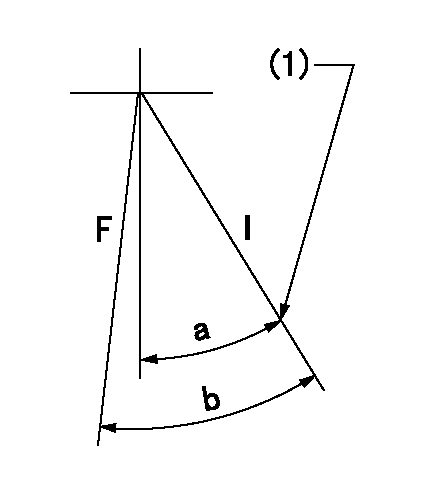
F:Full speed
I:Idle
(1)Stopper bolt set position 'H'
----------
----------
a=40deg+-5deg b=(48deg)+-3deg
----------
----------
a=40deg+-5deg b=(48deg)+-3deg
Stop lever angle

N:Pump normal
S:Stop the pump.
----------
----------
a=15deg+-5deg b=38.5deg+-5deg
----------
----------
a=15deg+-5deg b=38.5deg+-5deg
Timing setting

(1)Pump vertical direction
(2)Coupling's key groove position at No 1 cylinder's beginning of injection
(3)-
(4)-
----------
----------
a=(0deg)
----------
----------
a=(0deg)
Information:
Lubricant Viscosity Recommendations
See chart for recommended viscosity and temperature range. The required performance criteria for the oil is defined in the previous Lubricant Specification section.The minimum temperature for the viscosity grade provides guidelines for the lowest starting temperature with a "cold soaked" engine. Base stocks for blending the oil formulations do differ, and variations can exist within a viscosity grade on low temperature characteristics. Therefore, a particular oil may allow lower starting temperatures than given in the chart. Your oil supplier can provide additional information on oil properties.The recommendation is to use the highest viscosity oil possible. Even though the ambient temperature may be low, operating engines can still be subjected to normal oil temperatures because of regulated temperature components. Higher viscosity fluids provide better protection to all components contacted during the full day work cycle.Multi-viscosity oils are preferred because of full protection through a wider temperature range. See chart for recommended viscosity and temperature range.To determine if the oil in the crankcase will flow in cold weather, remove the oil dipstick before starting the engine. If the oil flows off, the oil is fluid enough to circulate properly.Lubricant Viscosity Chart
Refill Capacities
These refill capacities reflect the crankcase capacity plus filter. Auxiliary oil filter systems will require additional oil. For all auxiliary oil filter system information consult the OEM or auxiliary oil filter system manufacturer.In order to properly maintain the cooling system, Total Cooling System capacity must be known. This capacity information will be needed to determine the amount of antifreeze and coolant additive (conditioner) required for the cooling system.