Information injection-pump assembly
ZEXEL
106671-3810
1066713810
HINO
220004540A
220004540a
Rating:
Service parts 106671-3810 INJECTION-PUMP ASSEMBLY:
1.
_
7.
COUPLING PLATE
8.
_
9.
_
11.
Nozzle and Holder
12.
Open Pre:MPa(Kqf/cm2)
21.6(220)
15.
NOZZLE SET
Include in #1:
106671-3810
as INJECTION-PUMP ASSEMBLY
Cross reference number
ZEXEL
106671-3810
1066713810
HINO
220004540A
220004540a
Zexel num
Bosch num
Firm num
Name
106671-3810
220004540A HINO
INJECTION-PUMP ASSEMBLY
EK100 * K
EK100 * K
Calibration Data:
Adjustment conditions
Test oil
1404 Test oil ISO4113 or {SAEJ967d}
1404 Test oil ISO4113 or {SAEJ967d}
Test oil temperature
degC
40
40
45
Nozzle and nozzle holder
105780-8140
Bosch type code
EF8511/9A
Nozzle
105780-0000
Bosch type code
DN12SD12T
Nozzle holder
105780-2080
Bosch type code
EF8511/9
Opening pressure
MPa
17.2
Opening pressure
kgf/cm2
175
Injection pipe
Outer diameter - inner diameter - length (mm) mm 8-3-600
Outer diameter - inner diameter - length (mm) mm 8-3-600
Overflow valve
134424-0920
Overflow valve opening pressure
kPa
162
147
177
Overflow valve opening pressure
kgf/cm2
1.65
1.5
1.8
Tester oil delivery pressure
kPa
157
157
157
Tester oil delivery pressure
kgf/cm2
1.6
1.6
1.6
Direction of rotation (viewed from drive side)
Left L
Left L
Injection timing adjustment
Direction of rotation (viewed from drive side)
Left L
Left L
Injection order
1-4-2-6-
3-5
Pre-stroke
mm
3.3
3.24
3.3
Beginning of injection position
Drive side NO.1
Drive side NO.1
Difference between angles 1
Cal 1-4 deg. 60 59.75 60.25
Cal 1-4 deg. 60 59.75 60.25
Difference between angles 2
Cyl.1-2 deg. 120 119.75 120.25
Cyl.1-2 deg. 120 119.75 120.25
Difference between angles 3
Cal 1-6 deg. 180 179.75 180.25
Cal 1-6 deg. 180 179.75 180.25
Difference between angles 4
Cal 1-3 deg. 240 239.75 240.25
Cal 1-3 deg. 240 239.75 240.25
Difference between angles 5
Cal 1-5 deg. 300 299.75 300.25
Cal 1-5 deg. 300 299.75 300.25
Injection quantity adjustment
Adjusting point
A
Rack position
10.6
Pump speed
r/min
500
500
500
Average injection quantity
mm3/st.
129
126
132
Max. variation between cylinders
%
0
-4
4
Fixing the lever
*
Injection quantity adjustment_02
Adjusting point
B
Rack position
10.9
Pump speed
r/min
700
700
700
Average injection quantity
mm3/st.
139.5
137.5
141.5
Max. variation between cylinders
%
0
-2
2
Basic
*
Fixing the lever
*
Injection quantity adjustment_03
Adjusting point
C
Rack position
11.5+-0.
5
Pump speed
r/min
1100
1100
1100
Average injection quantity
mm3/st.
150
147
153
Max. variation between cylinders
%
0
-4
4
Fixing the lever
*
Injection quantity adjustment_04
Adjusting point
D
Rack position
7+-0.5
Pump speed
r/min
225
225
225
Average injection quantity
mm3/st.
15
12
18
Max. variation between cylinders
%
0
-15
15
Fixing the rack
*
Injection quantity adjustment_05
Adjusting point
E
Rack position
-
Pump speed
r/min
100
100
100
Average injection quantity
mm3/st.
126.3
119.3
133.3
Fixing the lever
*
Timer adjustment
Pump speed
r/min
750--
Advance angle
deg.
0
0
0
Remarks
Start
Start
Timer adjustment_02
Pump speed
r/min
700
Advance angle
deg.
0.5
Timer adjustment_03
Pump speed
r/min
900
Advance angle
deg.
1.4
0.9
1.9
Timer adjustment_04
Pump speed
r/min
1100
Advance angle
deg.
3.5
3
4
Timer adjustment_05
Pump speed
r/min
-
Advance angle
deg.
4
3.5
4.5
Remarks
Measure the actual speed, stop
Measure the actual speed, stop
Test data Ex:
Governor adjustment
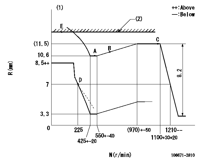
N:Pump speed
R:Rack position (mm)
(1)Damper spring setting: DL
(2)RACK LIMIT
----------
DL=6.2-0.2mm
----------
----------
DL=6.2-0.2mm
----------
Speed control lever angle

F:Full speed
----------
----------
a=3deg+-5deg
----------
----------
a=3deg+-5deg
0000000901

F:Full load
I:Idle
(1)Stopper bolt setting
----------
----------
a=10deg+-5deg b=27.5deg+-3deg
----------
----------
a=10deg+-5deg b=27.5deg+-3deg
Stop lever angle

N:Pump normal
S:Stop the pump.
----------
----------
a=15deg+-5deg b=64deg+-5deg
----------
----------
a=15deg+-5deg b=64deg+-5deg
0000001501 GOVERNOR TORQUE CONTROL
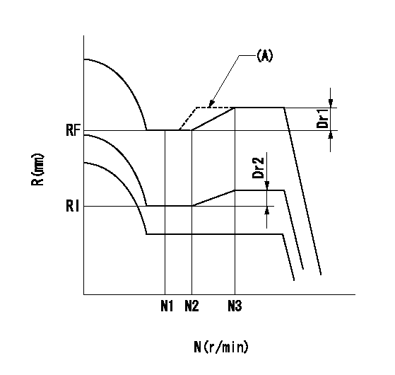
Dr:Torque control stroke
(A): Without torque control spring capsule
1. Adjustment procedures
(1)Procedure is the same as that for the RFD (former type), except that the positive torque control stroke must be determined at the full lever setting.
2. Procedures for adjustment
(1)Remove the torque control spring capsule.
(2)Operate the pump at approximately N1. (End of idling spring operation < N1.)
(3)Tilt the lever to the full side.
(4)Set so that R = RF.
(5)Increase the speed by pushing in the screw (attached to the bracket on the rear of the tension lever) through the adjusting window.
(6)Adjust so that the torque control stroke Dr1 can be obtained.
(7)Align N2 and N3 with the torque control spring capsule.
3. Final confirmation
(1)After final confirmation, temporarily set the load lever to N = N1, R = idling position.
(2)From this condition, increase speed to N = N4.
(3)Confirm that positive torque control stroke is Dr2.
----------
N1=500r/min N2=550+-40r/min N3=(970)+-50r/min N4=1050r/min RF=10.6mm RI=7mm Dr1=0.9mm Dr2=0+0.3mm
----------
----------
N1=500r/min N2=550+-40r/min N3=(970)+-50r/min N4=1050r/min RF=10.6mm RI=7mm Dr1=0.9mm Dr2=0+0.3mm
----------
Timing setting

(1)Pump vertical direction
(2)Coupling's key groove position at No 1 cylinder's beginning of injection
(3)-
(4)-
----------
----------
a=(0deg)
----------
----------
a=(0deg)
Information:
Adjustto conform and correspond to specifications.Checkto observe for satisfactory conditions, accuracy, safety or performance.Exchangeto trade a worn or failing component for a remanufactured or rebuilt component.Inspectto examine closely, in critical appraisal, while testing or evaluating components or systems.Inspect/Rebuild or Exchangeto examine closely, then making the decision on repair option (i.e. Rebuild or Exchange).Lubricateto apply a lubricant (oil, grease, etc.) as specified for reducing friction, heat and wear between solid surfaces.Protective Devicesindicators such as gauges, lights, emergency shutoffs, etc., that alert an operator that a potential problem may exist. Failure to respond to these indicators in a timely manner could result in serious engine damage.Rebuildto repair a worn or failing component with new parts, components and/or remanufactured components.Replaceto install something new, remanufactured or rebuilt in place of an existing worn or failing component.Service Hours (Electrical)records the time (clock hours) the engine is actually running but does not reflect variations in speed, load, etc. Some engines are equipped with mechanical service meters reading in Service Meter Units (SMU). The Maintenance Schedules are developed for clock hours or fuel consumption. For most users, clock hours are the standard interval for maintenance and SMU's can be roughly equal to clock hours. However, Caterpillar recommends that fuel consumption be used as the preferred method of determining intervals rather than SMU's or clock hours.Interval Categories
Engine components can generally be grouped into speed sensitive and load sensitive categories. The maintenance interval for each item listed in the Maintenance Schedule is based on either engine speed or load. Speed sensitive items such as water pumps and air compressors are not primarily affected by the operating load on your engine. The load on an engine will not significantly accelerate the repair or replacement cycle for speed sensitive items.The maintenance intervals established for speed sensitive items are based on service hours. Load sensitive items such as piston rings and cylinder liners are affected by the operating load on your engine. Generally speaking, the lower the load, the longer the engine life. Conversely, the higher the load, the shorter the engine life. A heavy load on an engine will accelerate the repair or replacement cycle for load sensitive items.Load sensitive items are normally internal engine components. The amount of fuel consumed is directly related to the load on your engine.The maintenance interval for load sensitive items includes fuel consumption, since the amount of fuel consumed is directly related to the load on your engine.Caterpillar recommends performing maintenance on load sensitive items at maintenance intervals based on the quantity of fuel consumed.
Engine components can generally be grouped into speed sensitive and load sensitive categories. The maintenance interval for each item listed in the Maintenance Schedule is based on either engine speed or load. Speed sensitive items such as water pumps and air compressors are not primarily affected by the operating load on your engine. The load on an engine will not significantly accelerate the repair or replacement cycle for speed sensitive items.The maintenance intervals established for speed sensitive items are based on service hours. Load sensitive items such as piston rings and cylinder liners are affected by the operating load on your engine. Generally speaking, the lower the load, the longer the engine life. Conversely, the higher the load, the shorter the engine life. A heavy load on an engine will accelerate the repair or replacement cycle for load sensitive items.Load sensitive items are normally internal engine components. The amount of fuel consumed is directly related to the load on your engine.The maintenance interval for load sensitive items includes fuel consumption, since the amount of fuel consumed is directly related to the load on your engine.Caterpillar recommends performing maintenance on load sensitive items at maintenance intervals based on the quantity of fuel consumed.
Have questions with 106671-3810?
Group cross 106671-3810 ZEXEL
Hino
106671-3810
220004540A
INJECTION-PUMP ASSEMBLY
EK100
EK100