Information injection-pump assembly
BOSCH
9 400 616 782
9400616782
ZEXEL
106671-3803
1066713803
HINO
220004513A
220004513a

Rating:
Cross reference number
BOSCH
9 400 616 782
9400616782
ZEXEL
106671-3803
1066713803
HINO
220004513A
220004513a
Zexel num
Bosch num
Firm num
Name
Calibration Data:
Adjustment conditions
Test oil
1404 Test oil ISO4113 or {SAEJ967d}
1404 Test oil ISO4113 or {SAEJ967d}
Test oil temperature
degC
40
40
45
Nozzle and nozzle holder
105780-8140
Bosch type code
EF8511/9A
Nozzle
105780-0000
Bosch type code
DN12SD12T
Nozzle holder
105780-2080
Bosch type code
EF8511/9
Opening pressure
MPa
17.2
Opening pressure
kgf/cm2
175
Injection pipe
Outer diameter - inner diameter - length (mm) mm 8-3-600
Outer diameter - inner diameter - length (mm) mm 8-3-600
Overflow valve (drive side)
134424-1420
Overflow valve opening pressure (drive side)
kPa
162
147
177
Overflow valve opening pressure (drive side)
kgf/cm2
1.65
1.5
1.8
Overflow valve (governor side)
134424-1520
Overflow valve opening pressure (governor side)
kPa
162
147
177
Overflow valve opening pressure (governor side)
kgf/cm2
1.65
1.5
1.8
Tester oil delivery pressure
kPa
157
157
157
Tester oil delivery pressure
kgf/cm2
1.6
1.6
1.6
Direction of rotation (viewed from drive side)
Right R
Right R
Injection timing adjustment
Direction of rotation (viewed from drive side)
Right R
Right R
Injection order
1-4-2-6-
3-5
Pre-stroke
mm
4.5
4.44
4.5
Beginning of injection position
Drive side NO.1
Drive side NO.1
Difference between angles 1
Cal 1-4 deg. 60 59.75 60.25
Cal 1-4 deg. 60 59.75 60.25
Difference between angles 2
Cyl.1-2 deg. 120 119.75 120.25
Cyl.1-2 deg. 120 119.75 120.25
Difference between angles 3
Cal 1-6 deg. 180 179.75 180.25
Cal 1-6 deg. 180 179.75 180.25
Difference between angles 4
Cal 1-3 deg. 240 239.75 240.25
Cal 1-3 deg. 240 239.75 240.25
Difference between angles 5
Cal 1-5 deg. 300 299.75 300.25
Cal 1-5 deg. 300 299.75 300.25
Injection quantity adjustment
Adjusting point
A
Rack position
7.9
Pump speed
r/min
700
700
700
Average injection quantity
mm3/st.
132.7
130.7
134.7
Max. variation between cylinders
%
0
-2
2
Basic
*
Fixing the lever
*
Boost pressure
kPa
33.3
33.3
Boost pressure
mmHg
250
250
Injection quantity adjustment_02
Adjusting point
B
Rack position
7.1+-0.5
Pump speed
r/min
1250
1250
1250
Average injection quantity
mm3/st.
111.4
107.4
115.4
Max. variation between cylinders
%
0
-5
5
Fixing the lever
*
Boost pressure
kPa
33.3
33.3
Boost pressure
mmHg
250
250
Injection quantity adjustment_03
Adjusting point
C
Rack position
7.9
Pump speed
r/min
1150
1150
1150
Average injection quantity
mm3/st.
133.7
130.7
136.7
Max. variation between cylinders
%
0
-5
5
Fixing the lever
*
Boost pressure
kPa
33.3
33.3
Boost pressure
mmHg
250
250
Injection quantity adjustment_04
Adjusting point
D
Rack position
8
Pump speed
r/min
500
500
500
Average injection quantity
mm3/st.
135.8
132.8
138.8
Max. variation between cylinders
%
0
-5
5
Fixing the lever
*
Boost pressure
kPa
33.3
33.3
Boost pressure
mmHg
250
250
Injection quantity adjustment_05
Adjusting point
E
Rack position
4.7+-0.5
Pump speed
r/min
225
225
225
Average injection quantity
mm3/st.
12.3
9.3
15.3
Max. variation between cylinders
%
0
-15
15
Fixing the rack
*
Boost pressure
kPa
0
0
0
Boost pressure
mmHg
0
0
0
Injection quantity adjustment_06
Adjusting point
F
Rack position
7.7+-0.5
Pump speed
r/min
100
100
100
Average injection quantity
mm3/st.
89
89
Fixing the lever
*
Boost pressure
kPa
0
0
0
Boost pressure
mmHg
0
0
0
Injection quantity adjustment_07
Adjusting point
G
Rack position
-
Pump speed
r/min
200
200
200
Average injection quantity
mm3/st.
156.3
156.3
166.3
Fixing the lever
*
Boost pressure
kPa
33.3
33.3
Boost pressure
mmHg
250
250
Injection quantity adjustment_08
Adjusting point
H
Rack position
6.1+-0.5
Pump speed
r/min
400
400
400
Average injection quantity
mm3/st.
67.3
65.3
69.3
Fixing the lever
*
Boost pressure
kPa
0
0
0
Boost pressure
mmHg
0
0
0
Boost compensator adjustment
Pump speed
r/min
700
700
700
Rack position
(6.1)
Boost pressure
kPa
3.3
3.3
5.3
Boost pressure
mmHg
25
25
40
Boost compensator adjustment_02
Pump speed
r/min
700
700
700
Rack position
7.9
Boost pressure
kPa
16
16
16
Boost pressure
mmHg
120
120
120
Timer adjustment
Pump speed
r/min
700+100
Advance angle
deg.
0
0
0
Remarks
Start
Start
Timer adjustment_02
Pump speed
r/min
1150
Advance angle
deg.
2.5
2.2
2.8
Remarks
Finish
Finish
Test data Ex:
Governor adjustment
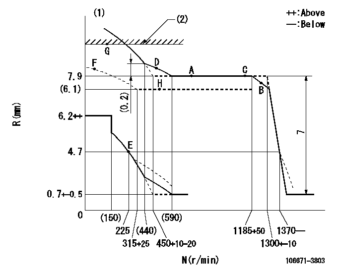
N:Pump speed
R:Rack position (mm)
(1)Damper spring setting: DL
(2)RACK LIMIT
----------
DL=4.2-0.2mm
----------
----------
DL=4.2-0.2mm
----------
Speed control lever angle

F:Full speed
----------
----------
a=7deg+-5deg
----------
----------
a=7deg+-5deg
0000000901
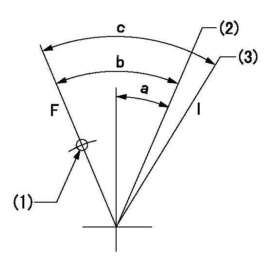
F:Full load
I:Idle
(1)Use the hole at R = aa
(2)Point E setting
(3)At delivery
----------
aa=54mm
----------
a=14deg+-5deg b=39deg+-3deg c=39deg+-5deg
----------
aa=54mm
----------
a=14deg+-5deg b=39deg+-3deg c=39deg+-5deg
Stop lever angle
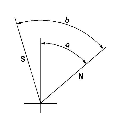
N:Pump normal
S:Stop the pump.
----------
----------
a=39deg+-5deg b=48.5deg+-5deg
----------
----------
a=39deg+-5deg b=48.5deg+-5deg
0000001501 Q ADJUSTMENT PIPING
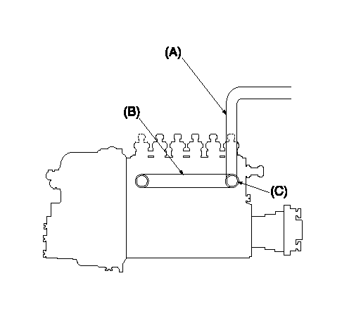
Tester fuel pipe A
Adjust screw A so that the timer advance angle determined in (B) can be obtained.
Fuel inlet C
Piping at standard injection quantity adjustment
1. Because the pump gallery is divided into two, be careful of the fuel piping at adjustment.
----------
----------
----------
----------
Timing setting

(1)Pump vertical direction
(2)Coupling's key groove position at No 1 cylinder's beginning of injection
(3)-
(4)-
----------
----------
a=(50deg)
----------
----------
a=(50deg)
Information:
Coolant is essential to control engine operating temperatures and make components last longer. Poorly maintained coolant can actually shorten component life by causing a chain reaction of heat problems. Excessive heat can cause: * Hot spots that crack steel, notably in cylinder heads* Bubble pockets that form on cylinder surfaces and result in liner pitting* Oil to degrade, leading to component damage* Lacquer and shellac build up on precision hydraulic parts* Oil additives to break down and transmission clutches to slipS O S Coolant Analysis is the best way to monitor the condition of your coolant and your cooling system. The two level program, based on samples you submit, shows the condition of coolant and the cooling system.Level I: Basic Coolant Maintenance Check
Checks for correct chemical balance for proper heat and corrosion control. Tests for: * glycol* SCA concentrations* pH* conductivityS O S Coolant Analysis reports results and makes recommendations, usually within 24 hours.The concentration of SCA should be checked regularly for overconcentration or underconcentration. This should be done with test kits, or S O S Coolant Analysis (Level I) at the Every 250 Service Hours interval.Further coolant analysis is recommended at twice a year or after every 1000 service hours.For example, suppose considerable deposits are found in the water jacket areas on the external cooling system, yet coolant additive concentrations were carefully maintained. Chances are that the coolant water had minerals which deposited on the engine over time.One way to verify the water condition, or to be sure of new water at fill time, is to have a coolant analysis conducted. Full water analysis can sometimes be obtained locally by contacting your local water utility company or an agricultural agent. Private laboratories are also available.Caterpillar recommends S O S Level II Coolant Analysis.Level II: Comprehensive Cooling System Analysis
Completely analyzes coolant and coolant effects on the cooling system. Level II Analysis provides: * full Level I analysis* visual properties inspection* metal corrosion and contaminant identification* identification of built up impurities that point to corrosion and scaling problems BEFORE they lead to costly repairs.Level II Analysis provides a simple, clear report of results, and makes recommendations for the lowest cost corrective options.For more information of coolant analysis and how it can help manage your equipment, see your Caterpillar dealer. Consult your Caterpillar dealer for complete information and assistance in establishing an S O S analysis program for your engine(s).