Information injection-pump assembly
ZEXEL
106671-3800
1066713800
HINO
220004510A
220004510a
Rating:
Cross reference number
ZEXEL
106671-3800
1066713800
HINO
220004510A
220004510a
Zexel num
Bosch num
Firm num
Name
Calibration Data:
Adjustment conditions
Test oil
1404 Test oil ISO4113 or {SAEJ967d}
1404 Test oil ISO4113 or {SAEJ967d}
Test oil temperature
degC
40
40
45
Nozzle and nozzle holder
105780-8140
Bosch type code
EF8511/9A
Nozzle
105780-0000
Bosch type code
DN12SD12T
Nozzle holder
105780-2080
Bosch type code
EF8511/9
Opening pressure
MPa
17.2
Opening pressure
kgf/cm2
175
Injection pipe
Outer diameter - inner diameter - length (mm) mm 8-3-600
Outer diameter - inner diameter - length (mm) mm 8-3-600
Overflow valve (drive side)
134424-1420
Overflow valve opening pressure (drive side)
kPa
162
147
177
Overflow valve opening pressure (drive side)
kgf/cm2
1.65
1.5
1.8
Overflow valve (governor side)
134424-1520
Overflow valve opening pressure (governor side)
kPa
162
147
177
Overflow valve opening pressure (governor side)
kgf/cm2
1.65
1.5
1.8
Tester oil delivery pressure
kPa
157
157
157
Tester oil delivery pressure
kgf/cm2
1.6
1.6
1.6
Direction of rotation (viewed from drive side)
Right R
Right R
Injection timing adjustment
Direction of rotation (viewed from drive side)
Right R
Right R
Injection order
1-4-2-6-
3-5
Pre-stroke
mm
4.5
4.44
4.5
Beginning of injection position
Drive side NO.1
Drive side NO.1
Difference between angles 1
Cal 1-4 deg. 60 59.75 60.25
Cal 1-4 deg. 60 59.75 60.25
Difference between angles 2
Cyl.1-2 deg. 120 119.75 120.25
Cyl.1-2 deg. 120 119.75 120.25
Difference between angles 3
Cal 1-6 deg. 180 179.75 180.25
Cal 1-6 deg. 180 179.75 180.25
Difference between angles 4
Cal 1-3 deg. 240 239.75 240.25
Cal 1-3 deg. 240 239.75 240.25
Difference between angles 5
Cal 1-5 deg. 300 299.75 300.25
Cal 1-5 deg. 300 299.75 300.25
Injection quantity adjustment
Adjusting point
A
Rack position
7.9
Pump speed
r/min
700
700
700
Average injection quantity
mm3/st.
132.7
130.7
134.7
Max. variation between cylinders
%
0
-2
2
Basic
*
Fixing the lever
*
Boost pressure
kPa
33.3
33.3
Boost pressure
mmHg
250
250
Injection quantity adjustment_02
Adjusting point
B
Rack position
7.1+-0.5
Pump speed
r/min
1250
1250
1250
Average injection quantity
mm3/st.
111.4
107.4
115.4
Max. variation between cylinders
%
0
-5
5
Fixing the lever
*
Boost pressure
kPa
33.3
33.3
Boost pressure
mmHg
250
250
Injection quantity adjustment_03
Adjusting point
C
Rack position
7.9
Pump speed
r/min
1150
1150
1150
Average injection quantity
mm3/st.
133.7
130.7
136.7
Max. variation between cylinders
%
0
-5
5
Fixing the lever
*
Boost pressure
kPa
33.3
33.3
Boost pressure
mmHg
250
250
Injection quantity adjustment_04
Adjusting point
D
Rack position
8
Pump speed
r/min
500
500
500
Average injection quantity
mm3/st.
135.8
132.8
138.8
Max. variation between cylinders
%
0
-5
5
Fixing the lever
*
Boost pressure
kPa
33.3
33.3
Boost pressure
mmHg
250
250
Injection quantity adjustment_05
Adjusting point
E
Rack position
4.7+-0.5
Pump speed
r/min
225
225
225
Average injection quantity
mm3/st.
12.3
9.3
15.3
Max. variation between cylinders
%
0
-15
15
Fixing the rack
*
Boost pressure
kPa
0
0
0
Boost pressure
mmHg
0
0
0
Injection quantity adjustment_06
Adjusting point
F
Rack position
7.7+-0.5
Pump speed
r/min
100
100
100
Average injection quantity
mm3/st.
89
89
Fixing the lever
*
Boost pressure
kPa
0
0
0
Boost pressure
mmHg
0
0
0
Injection quantity adjustment_07
Adjusting point
G
Rack position
-
Pump speed
r/min
200
200
200
Average injection quantity
mm3/st.
156.3
156.3
166.3
Fixing the lever
*
Boost pressure
kPa
33.3
33.3
Boost pressure
mmHg
250
250
Injection quantity adjustment_08
Adjusting point
H
Rack position
6.1+-0.5
Pump speed
r/min
400
400
400
Average injection quantity
mm3/st.
67.3
65.3
69.3
Fixing the lever
*
Boost pressure
kPa
0
0
0
Boost pressure
mmHg
0
0
0
Boost compensator adjustment
Pump speed
r/min
700
700
700
Rack position
(6.1)
Boost pressure
kPa
3.3
3.3
5.3
Boost pressure
mmHg
25
25
40
Boost compensator adjustment_02
Pump speed
r/min
700
700
700
Rack position
7.9
Boost pressure
kPa
16
16
16
Boost pressure
mmHg
120
120
120
Timer adjustment
Pump speed
r/min
975--
Advance angle
deg.
0
0
0
Remarks
Start
Start
Timer adjustment_02
Pump speed
r/min
925
Advance angle
deg.
0.3
Timer adjustment_03
Pump speed
r/min
1050
Advance angle
deg.
1.3
0.8
1.8
Timer adjustment_04
Pump speed
r/min
1150
Advance angle
deg.
2.5
2.2
2.8
Remarks
Finish
Finish
Test data Ex:
Governor adjustment

N:Pump speed
R:Rack position (mm)
(1)Damper spring setting: DL
(2)RACK LIMIT
----------
DL=4.2-0.2mm
----------
----------
DL=4.2-0.2mm
----------
Speed control lever angle

F:Full speed
----------
----------
a=7deg+-5deg
----------
----------
a=7deg+-5deg
0000000901
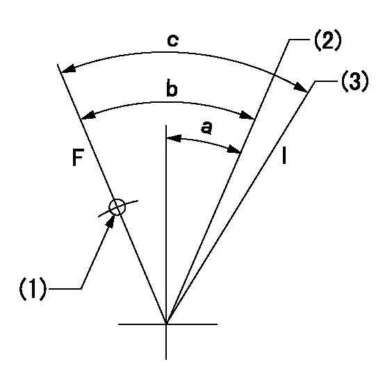
F:Full load
I:Idle
(1)Use the hole at R = aa
(2)Point E setting
(3)At delivery
----------
aa=54mm
----------
a=14deg+-5deg b=39deg+-3deg c=39deg+-5deg
----------
aa=54mm
----------
a=14deg+-5deg b=39deg+-3deg c=39deg+-5deg
Stop lever angle

N:Pump normal
S:Stop the pump.
----------
----------
a=39deg+-5deg b=48.5deg+-5deg
----------
----------
a=39deg+-5deg b=48.5deg+-5deg
Timing setting

(1)Pump vertical direction
(2)Coupling's key groove position at No 1 cylinder's beginning of injection
(3)-
(4)-
----------
----------
a=(50deg)
----------
----------
a=(50deg)
Information:
Air-to-air aftercooling (ATAAC) systems are simple, reliable, and easy to maintain. Generally, ATAAC benefits one or two of the following areas: * Improved fuel consumption* Lower emissions* Increased power In some cases all three may be improved.Operation of ATAAC
Inlet air is pulled through the air cleaner, compressed and heated by the compressor wheel in the compressor side of the turbocharger to about 150°C (300°F). The heated air is then pushed through the air to air aftercooler core and moved to the air inlet manifold in the cylinder head at about 43°C (110°F).
Radiator Core (1) and Aftercooler Core (2).Cooling the inlet air increases combustion efficiency, which helps to lower fuel consumption and increase horsepower output. The aftercooler core (2) is a separate cooler core installed behind the standard radiator core (1). Ambient temperature is moved across both cores by the engine fan- this cools the turbocharged inlet air and the engine coolant.Lower inlet air temperature allows more air to enter the cylinder. More complete fuel combustion and reduced exhaust emissions are the results. Air-to-air aftercoolers can achieve charge air temperatures lower than water-to-air systems. The lower air temperatures provide improved efficiency.
To maintain an adequate water pump cavitation temperature for efficient water pump performance in an Air-to-Air Aftercooled engine: Caterpillar recommends that the coolant mix contain a minimum of 30 percent Caterpillar Antifreeze, or equivalent.
Air Inlet System
An air hose failure or a significant air inlet system leak will cause a large drop in boost pressure and power. The engine can be operated at this power level for a short period of time, however, sustained operation under this condition should be avoided.A slight reduction in power or response, or a small increase in exhaust temperature may indicate a small air leak in the charge air cooler core or piping.If air leaking is suspected, inspect the air inlet hoses, elbows and gaskets for cracks or damage. Replace the parts as needed. Check for loose clamps and tighten the clamps as needed.Radiator Restrictions
Caterpillar discourages the use of air flow restriction devices mounted in front of radiators with air-to-air aftercooled engines. Air flow restriction can cause higher exhaust temperatures, power loss, excessive fan usage, and a reduction in fuel economy.If an air flow restriction device must be used, the device should have a permanent opening directly in line with the fan hub. The device must have a minimum opening dimension of at least 770 cm2 (120 in2).A centered opening, directly in line with the fan hub, is specified to provide sensing when viscous fan drives are used and/or to prevent an interrupted air flow on the fan blades. Interrupted air flow on the fan blades could cause a fan failure.Caterpillar recommends that a package include an inlet manifold temperature device, such as a light indicator, buzzer, etc., set at 65°C (150°F) and/or installation of an inlet air temperature gauge. For the ATAAC (Air-To-Air Aftercooled) engines, air temperature in the inlet manifold should not exceed 65°C (150°F). Temperatures exceeding this limit can cause power loss