Information injection-pump assembly
ZEXEL
106671-3792
1066713792
HINO
220201864A
220201864a

Rating:
Cross reference number
ZEXEL
106671-3792
1066713792
HINO
220201864A
220201864a
Zexel num
Bosch num
Firm num
Name
Calibration Data:
Adjustment conditions
Test oil
1404 Test oil ISO4113 or {SAEJ967d}
1404 Test oil ISO4113 or {SAEJ967d}
Test oil temperature
degC
40
40
45
Nozzle and nozzle holder
105780-8140
Bosch type code
EF8511/9A
Nozzle
105780-0000
Bosch type code
DN12SD12T
Nozzle holder
105780-2080
Bosch type code
EF8511/9
Opening pressure
MPa
17.2
Opening pressure
kgf/cm2
175
Injection pipe
Outer diameter - inner diameter - length (mm) mm 8-3-600
Outer diameter - inner diameter - length (mm) mm 8-3-600
Overflow valve (drive side)
134424-1420
Overflow valve opening pressure (drive side)
kPa
162
147
177
Overflow valve opening pressure (drive side)
kgf/cm2
1.65
1.5
1.8
Overflow valve (governor side)
134424-1720
Overflow valve opening pressure (governor side)
kPa
162
147
177
Overflow valve opening pressure (governor side)
kgf/cm2
1.65
1.5
1.8
Tester oil delivery pressure
kPa
157
157
157
Tester oil delivery pressure
kgf/cm2
1.6
1.6
1.6
Direction of rotation (viewed from drive side)
Right R
Right R
Injection timing adjustment
Direction of rotation (viewed from drive side)
Right R
Right R
Injection order
1-4-2-6-
3-5
Pre-stroke
mm
4.5
4.4
4.5
Beginning of injection position
Drive side NO.1
Drive side NO.1
Difference between angles 1
Cal 1-4 deg. 60 59.5 60.5
Cal 1-4 deg. 60 59.5 60.5
Difference between angles 2
Cyl.1-2 deg. 120 119.5 120.5
Cyl.1-2 deg. 120 119.5 120.5
Difference between angles 3
Cal 1-6 deg. 180 179.5 180.5
Cal 1-6 deg. 180 179.5 180.5
Difference between angles 4
Cal 1-3 deg. 240 239.5 240.5
Cal 1-3 deg. 240 239.5 240.5
Difference between angles 5
Cal 1-5 deg. 300 299.5 300.5
Cal 1-5 deg. 300 299.5 300.5
Injection quantity adjustment
Adjusting point
A
Rack position
7.8
Pump speed
r/min
800
800
800
Average injection quantity
mm3/st.
109.8
107.8
111.8
Max. variation between cylinders
%
0
-2
2
Basic
*
Fixing the lever
*
Injection quantity adjustment_02
Adjusting point
B
Rack position
5.3+-0.5
Pump speed
r/min
360
360
360
Average injection quantity
mm3/st.
10
7
13
Max. variation between cylinders
%
0
-15
15
Fixing the rack
*
Injection quantity adjustment_03
Adjusting point
C
Rack position
-
Pump speed
r/min
100
100
100
Average injection quantity
mm3/st.
140
135
145
Fixing the lever
*
Rack limit
*
Timer adjustment
Pump speed
r/min
975--
Advance angle
deg.
0
0
0
Remarks
Start
Start
Timer adjustment_02
Pump speed
r/min
925
Advance angle
deg.
0.3
Timer adjustment_03
Pump speed
r/min
1000
Advance angle
deg.
0.8
0.3
1.3
Timer adjustment_04
Pump speed
r/min
-
Advance angle
deg.
2.5
2.5
2.5
Remarks
Measure the actual speed, stop
Measure the actual speed, stop
Test data Ex:
Governor adjustment
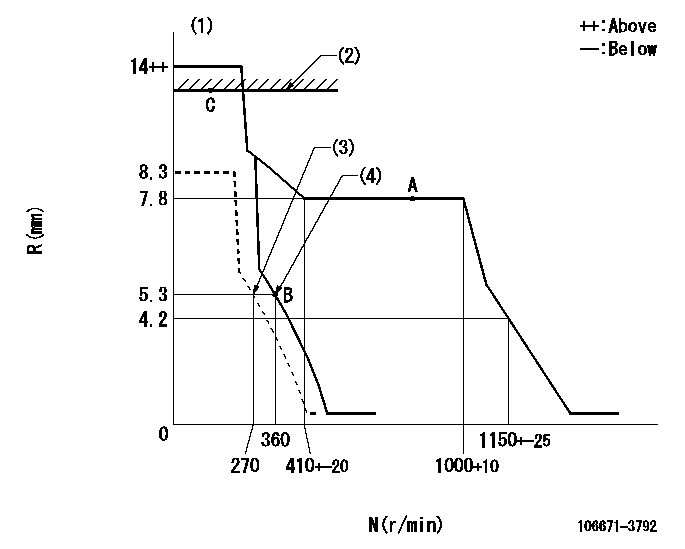
N:Pump speed
R:Rack position (mm)
(1)Target notch: K
(2)RACK LIMIT
(3)Set idle sub-spring
(4)Main spring setting
----------
K=17
----------
----------
K=17
----------
Speed control lever angle

F:Full speed
I:Idle
(1)Stopper bolt setting
----------
----------
a=11deg+-5deg b=17deg+-5deg
----------
----------
a=11deg+-5deg b=17deg+-5deg
Stop lever angle
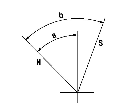
N:Pump normal
S:Stop the pump.
----------
----------
a=53deg+-5deg b=53deg+-5deg
----------
----------
a=53deg+-5deg b=53deg+-5deg
Timing setting

(1)Pump vertical direction
(2)Coupling's key groove position at No 1 cylinder's beginning of injection
(3)-
(4)-
----------
----------
a=(40deg)
----------
----------
a=(40deg)
Information:
Caterpillar Diesel Engines can operate effectively in cold weather. However, engine operation in cold weather is dependent on the type of fuel used and how well the fuel moves through fuel related components. The purpose of this section is to explain some of the problems and steps that can be taken to minimize fuel problems during cold weather operation, when the engine area is colder than 5°C (40°F).Fuel and the Effect from Cold Weather
The two types of diesel fuel available for your engine are typically grades No. 1 and No. 2. No. 2 diesel fuel is the most commonly used fuel. No. 1 diesel fuel, or a blend of No. 1 and No. 2, is best suited for cold weather operation.Quantities of No. 1 diesel fuel are limited, and generally only available during the winter months in the colder climates. During cold weather operation, if No. 1 fuel is unavailable, it may be necessary to use No. 2 diesel fuel.There are three major differences between No. 1 and No. 2 diesel fuel. No. 1 diesel fuel has: * a lower cloud point* a lower pour point* a lower BTU (kJ) (heat content) rating per unit volume of fuel than the average No. 2 diesel fuel.When using No. 1 diesel fuel, you may notice a drop in power and fuel efficiency. You should not experience any other operating effects.The cloud point is the temperature at which a cloud or haze of wax crystals begins to form in the fuel and cause fuel filters to plug. The pour point is the temperature which diesel fuel begins to thicken and be more resistant to flow through fuel pumps and lines.Be aware of these fuel values when purchasing your diesel fuel. Anticipate the average outside (ambient) temperature for the area your engine will be operating. Engines fueled in one climate may not operate satisfactorily if moved to another because of problems that result from cold weather.Before troubleshooting for low power or poor performance in winter months, check the type of fuel being used.When No. 2 diesel fuel is used: starting aids, engine oil pan heaters, engine coolant heaters, fuel heaters, and fuel line insulation also provide a means of minimizing starting and fuel problems in cold weather.Fuel Related Components in Cold Weather
Fuel Tanks
Condensation can form in partially filled fuel tanks. Top off fuel tanks before leaving overnight.Fuel tanks should contain some provision for draining water and sediment from the bottom of the tanks. Some fuel tanks use supply pipes that allow water and sediment to settle below the end of the fuel supply pipe.Some fuel tanks use supply lines that take fuel directly from the bottom of the tank. If equipped with this system, regular maintenance of the fuel system filter(s) is important.Check the fuel level in the day tank daily by observing the sight gauge. Drain the water and sediment from any fuel storage tank weekly, at the oil change period, and before the fuel tank is refilled. This will help