Information injection-pump assembly
ZEXEL
106671-3770
1066713770
HINO
220004440A
220004440a
Rating:
Cross reference number
ZEXEL
106671-3770
1066713770
HINO
220004440A
220004440a
Zexel num
Bosch num
Firm num
Name
Calibration Data:
Adjustment conditions
Test oil
1404 Test oil ISO4113 or {SAEJ967d}
1404 Test oil ISO4113 or {SAEJ967d}
Test oil temperature
degC
40
40
45
Nozzle and nozzle holder
105780-8140
Bosch type code
EF8511/9A
Nozzle
105780-0000
Bosch type code
DN12SD12T
Nozzle holder
105780-2080
Bosch type code
EF8511/9
Opening pressure
MPa
17.2
Opening pressure
kgf/cm2
175
Injection pipe
Outer diameter - inner diameter - length (mm) mm 6-2-600
Outer diameter - inner diameter - length (mm) mm 6-2-600
Overflow valve
134424-0920
Overflow valve opening pressure
kPa
162
147
177
Overflow valve opening pressure
kgf/cm2
1.65
1.5
1.8
Tester oil delivery pressure
kPa
157
157
157
Tester oil delivery pressure
kgf/cm2
1.6
1.6
1.6
Direction of rotation (viewed from drive side)
Left L
Left L
Injection timing adjustment
Direction of rotation (viewed from drive side)
Left L
Left L
Injection order
1-4-2-6-
3-5
Pre-stroke
mm
4.8
4.74
4.8
Beginning of injection position
Drive side NO.1
Drive side NO.1
Difference between angles 1
Cal 1-4 deg. 60 59.75 60.25
Cal 1-4 deg. 60 59.75 60.25
Difference between angles 2
Cyl.1-2 deg. 120 119.75 120.25
Cyl.1-2 deg. 120 119.75 120.25
Difference between angles 3
Cal 1-6 deg. 180 179.75 180.25
Cal 1-6 deg. 180 179.75 180.25
Difference between angles 4
Cal 1-3 deg. 240 239.75 240.25
Cal 1-3 deg. 240 239.75 240.25
Difference between angles 5
Cal 1-5 deg. 300 299.75 300.25
Cal 1-5 deg. 300 299.75 300.25
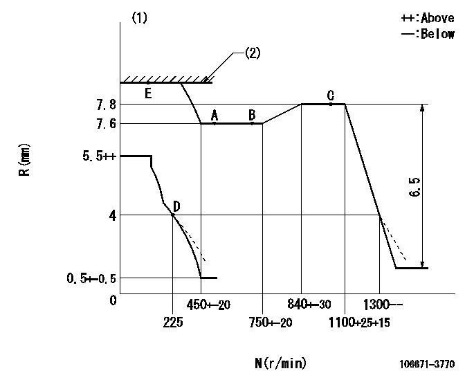
Injection quantity adjustment
Adjusting point
A
Rack position
7.6
Pump speed
r/min
500
500
500
Average injection quantity
mm3/st.
145.1
142.1
148.1
Max. variation between cylinders
%
0
-4
4
Fixing the lever
*
Injection quantity adjustment_02
Adjusting point
B
Rack position
7.6
Pump speed
r/min
700
700
700
Average injection quantity
mm3/st.
142.6
140.6
144.6
Max. variation between cylinders
%
0
-2
2
Basic
*
Fixing the lever
*
Injection quantity adjustment_03
Adjusting point
C
Rack position
7.8
Pump speed
r/min
1075
1075
1075
Average injection quantity
mm3/st.
148.2
145.2
151.2
Max. variation between cylinders
%
0
-4
4
Fixing the lever
*
Injection quantity adjustment_04
Adjusting point
D
Rack position
4+-0.5
Pump speed
r/min
225
225
225
Average injection quantity
mm3/st.
13
10
16
Max. variation between cylinders
%
0
-15
15
Fixing the rack
*
Injection quantity adjustment_05
Adjusting point
E
Rack position
8.6+-0.5
Pump speed
r/min
100
100
100
Average injection quantity
mm3/st.
140
140
150
Fixing the lever
*
Rack limit
*
Timer adjustment
Pump speed
r/min
865+50
Advance angle
deg.
0
0
0
Remarks
Start
Start
Timer adjustment_02
Pump speed
r/min
1075
Advance angle
deg.
4.5
4
5
Remarks
Finish
Finish
Test data Ex:
Governor adjustment
N:Pump speed
R:Rack position (mm)
(1)Damper spring setting: DL
(2)RACK LIMIT
----------
DL=3.3-0.2mm
----------
----------
DL=3.3-0.2mm
----------
Speed control lever angle

F:Full speed
----------
----------
a=17deg+-5deg
----------
----------
a=17deg+-5deg
0000000901
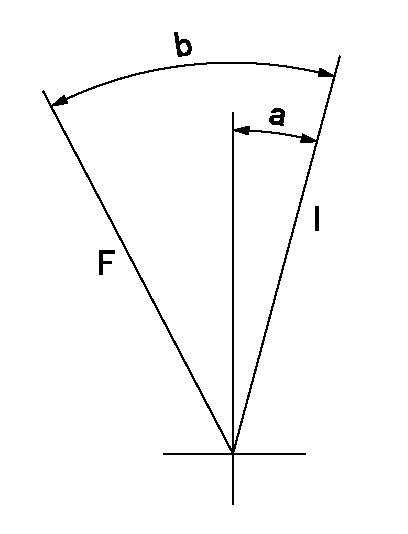
F:Full load
I:Idle
----------
----------
a=21deg+-5deg b=38deg+-3deg
----------
----------
a=21deg+-5deg b=38deg+-3deg
Stop lever angle
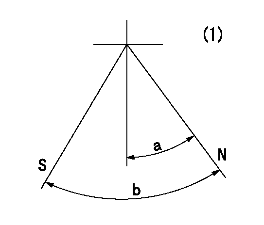
N:Pump normal
S:Stop the pump.
(1)Drive side viewed from upper left hand side.
----------
----------
a=40deg+-5deg b=64deg+-5deg
----------
----------
a=40deg+-5deg b=64deg+-5deg
0000001501 MICRO SWITCH
Switch adjustment
Adjust the bolt so that the lower lever position is obtained when the switch is turned ON.
(1)Speed N1
(2)Rack position Ra
----------
N1=300+25r/min Ra=4mm
----------
----------
N1=300+25r/min Ra=4mm
----------
Timing setting

(1)Pump vertical direction
(2)Coupling's key groove position at No 1 cylinder's beginning of injection
(3)-
(4)-
----------
----------
a=(0deg)
----------
----------
a=(0deg)
Information:
General Torque Information
Mismatched or incorrect fasteners can result in damage or malfunction, or possible injury.Take care to avoid mixing metric dimensioned fasteners and inch dimensioned fasteners.
Exceptions to these torques are given in the Service Manual, if necessary.Prior to installing any hardware, ensure that the components are in near new condition. Bolts and threads must nor be worn or damaged. Threads must not have burrs or nicks. Hardware must be free of rust and corrosion. Clean the hardware with a noncorrosive cleaner. Do not lubricate the fastener threads except with rust preventive. The rust preventive should be applied by the supplier of that component for purposes of shipping and storage. Other applications for lubricating components may also be specified in the Service Manual.For additional torque specifications, refer to SENR3130, Torque Specifications, available from your Caterpillar dealer.Standard Torque for Bolts, Nuts and Taperlock Studs
Torques for Taperlock Studs
Use these standard torque values for all fasteners unless otherwise specified in this manual or in the Service Manual.Torque for Metric Fasteners
Torque for Standard Hose Clamps-Worm Drive Band Type
The chart that follows gives the torques for initial installation of hose clamps on new hose and for reassembly or tightening of hose clamps on existing hose.
Torque for Constant Torque Hose Clamps
A constant torque hose clamp can be used in place of any standard hose clamp. Make sure the constant torque hose clamp is the same size as the standard clamp. Due to extreme temperature changes, hose will heat set. Heat setting causes hose clamps to loosen. Loose hose clamps can result in leaks. There have been reports of component failures caused by hose clamps loosening. The constant torque hose clamp will help prevent these failures. Use a torque wrench for proper installation of the constant torque hose clamp. The constant torque hose clamp is installed correctly under the following conditions: * Screw tip (1) extends 6.35 mm (.250 in) (X) beyond the housing.* The belleville washers are collapsed nearly flat after screw (2) is tightened to a torque of 11 1 N m (98 9 lb in).