Information injection-pump assembly
ZEXEL
106671-3741
1066713741
HINO
220004221B
220004221b
Rating:
Cross reference number
ZEXEL
106671-3741
1066713741
HINO
220004221B
220004221b
Zexel num
Bosch num
Firm num
Name
Calibration Data:
Adjustment conditions
Test oil
1404 Test oil ISO4113 or {SAEJ967d}
1404 Test oil ISO4113 or {SAEJ967d}
Test oil temperature
degC
40
40
45
Nozzle and nozzle holder
105780-8140
Bosch type code
EF8511/9A
Nozzle
105780-0000
Bosch type code
DN12SD12T
Nozzle holder
105780-2080
Bosch type code
EF8511/9
Opening pressure
MPa
17.2
Opening pressure
kgf/cm2
175
Injection pipe
Outer diameter - inner diameter - length (mm) mm 8-3-600
Outer diameter - inner diameter - length (mm) mm 8-3-600
Overflow valve
134424-0920
Overflow valve opening pressure
kPa
162
147
177
Overflow valve opening pressure
kgf/cm2
1.65
1.5
1.8
Tester oil delivery pressure
kPa
157
157
157
Tester oil delivery pressure
kgf/cm2
1.6
1.6
1.6
Direction of rotation (viewed from drive side)
Left L
Left L
Injection timing adjustment
Direction of rotation (viewed from drive side)
Left L
Left L
Injection order
1-4-2-6-
3-5
Pre-stroke
mm
4.8
4.74
4.8
Beginning of injection position
Drive side NO.1
Drive side NO.1
Difference between angles 1
Cal 1-4 deg. 60 59.75 60.25
Cal 1-4 deg. 60 59.75 60.25
Difference between angles 2
Cyl.1-2 deg. 120 119.75 120.25
Cyl.1-2 deg. 120 119.75 120.25
Difference between angles 3
Cal 1-6 deg. 180 179.75 180.25
Cal 1-6 deg. 180 179.75 180.25
Difference between angles 4
Cal 1-3 deg. 240 239.75 240.25
Cal 1-3 deg. 240 239.75 240.25
Difference between angles 5
Cal 1-5 deg. 300 299.75 300.25
Cal 1-5 deg. 300 299.75 300.25
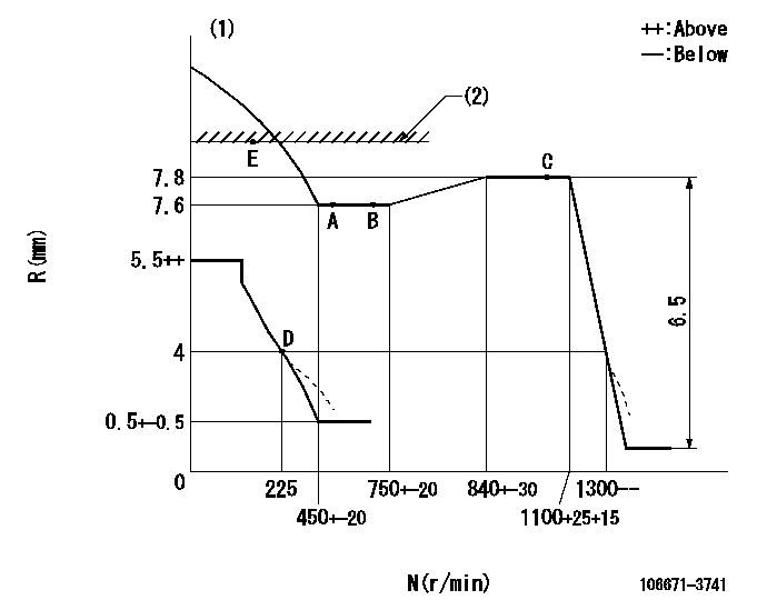
Injection quantity adjustment
Adjusting point
A
Rack position
7.6
Pump speed
r/min
500
500
500
Average injection quantity
mm3/st.
145.1
142.1
148.1
Max. variation between cylinders
%
0
-4
4
Fixing the lever
*
Injection quantity adjustment_02
Adjusting point
B
Rack position
7.6
Pump speed
r/min
700
700
700
Average injection quantity
mm3/st.
142.6
140.6
144.6
Max. variation between cylinders
%
0
-2
2
Basic
*
Fixing the lever
*
Injection quantity adjustment_03
Adjusting point
C
Rack position
7.8
Pump speed
r/min
1075
1075
1075
Average injection quantity
mm3/st.
148.2
145.2
151.2
Max. variation between cylinders
%
0
-4
4
Fixing the lever
*
Injection quantity adjustment_04
Adjusting point
D
Rack position
4+-0.5
Pump speed
r/min
225
225
225
Average injection quantity
mm3/st.
13
10
16
Max. variation between cylinders
%
0
-15
15
Fixing the rack
*
Injection quantity adjustment_05
Adjusting point
E
Rack position
8.6+-0.5
Pump speed
r/min
100
100
100
Average injection quantity
mm3/st.
140
140
150
Fixing the lever
*
Rack limit
*
Timer adjustment
Pump speed
r/min
865+50
Advance angle
deg.
0
0
0
Remarks
Start
Start
Timer adjustment_02
Pump speed
r/min
1075
Advance angle
deg.
4.5
4.2
4.8
Remarks
Finish
Finish
Test data Ex:
Governor adjustment
N:Pump speed
R:Rack position (mm)
(1)Beginning of damper spring operation: DL
(2)RACK LIMIT: RAL
----------
DL=3.3-0.2mm RAL=(8.6)mm
----------
----------
DL=3.3-0.2mm RAL=(8.6)mm
----------
Speed control lever angle

F:Full speed
----------
----------
a=17deg+-5deg
----------
----------
a=17deg+-5deg
0000000901
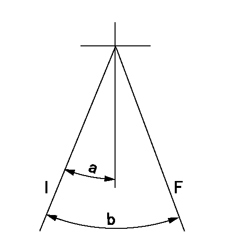
F:Full load
I:Idle
----------
----------
a=17deg+-5deg b=38deg+-3deg
----------
----------
a=17deg+-5deg b=38deg+-3deg
Stop lever angle

N:Pump normal
S:Stop the pump.
----------
----------
a=40deg+-5deg b=64deg+-5deg
----------
----------
a=40deg+-5deg b=64deg+-5deg
0000001501 MICRO SWITCH
Switch adjustment
Adjust the bolt so that the lower lever position is obtained when the switch is turned ON.
(1)Speed N1
(2)Rack position Ra
----------
N1=300+25r/min Ra=4mm
----------
----------
N1=300+25r/min Ra=4mm
----------
Timing setting

(1)Pump vertical direction
(2)Coupling's key groove position at No 1 cylinder's beginning of injection
(3)-
(4)-
----------
----------
a=(0deg)
----------
----------
a=(0deg)
Information:
Maintenance RecommendationsCaterpillar Inc. truck engines are certified by the United States Environmental Protection Agency (EPA) to comply with smoke and gaseous emission standards prescribed by Federal laws at the time of manufacture.Efficiency of emission control and engine performance depends on adherence to proper operation and maintenance recommendations AND use of recommended fuels and lubricating oils. It is recommended that major adjustments and repair be made by your authorized Caterpillar dealer.Various chemical fuel additives claiming to reduce visible smoke are available commercially. Although additives have been used by individuals to solve some isolated smoke problems in the field, they are not recommended for general use. Federal smoke regulations require that engines be certified without smoke depressants.The corrective steps taken immediately on discovery of worn parts, which may affect emission levels, will help assure proper operation of emission control systems. The use of genuine Caterpillar parts is recommended. Suppliers of non-Caterpillar parts must assure the owner that the use of such parts will not adversely affect emission levels.Regular maintenance intervals, along with special emphasis on the following items, are necessary to keep exhaust emissions within acceptable limits for the useful life of the engine. Refer to the Maintenance Management Schedule and Maintenance Section of this manual for details. If the engine is operating under severe conditions, adjust the maintenance schedule accordingly. See your authorized Caterpillar dealer to help analyze your specific application, operating environment and maintenance schedule adjustments.The following is an explanation of maintenance for emission-related components. See the Maintenance Management Schedule for the specific interval for the following items. FUEL INJECTION NOZZLES - Damaged fuel nozzles will normally cause the engine to misfire, run rough and smoke. Test and replace if necessary as recommended in the Maintenance Management Schedule. Fuel nozzles can be tested by an authorized Caterpillar truck engine dealer. TURBOCHARGER - Check for any unusual sound or vibration in the turbocharger. Inspect inlet and exhaust piping and connections. Check bearing condition and perform maintenance as described in the Maintenance Management Schedule.Owner is encouraged to keep adequate maintenance records, but the absence of such, in and of itself, will not invalidate the warranty.The vehicle owner may perform routine maintenance, repairs and other non warranty work or have it done at any repair facility. Such non warranty work need not be performed at a designated warranty station in order for the warranty to remain in force. Customer AssistanceCaterpillar Inc. aims to ensure that the Emission Control Systems warranty is properly administered. In the event that you do not receive the warranty service to which you believe you are entitled under the Emission Control Systems Warranty, call or write:Caterpillar Inc.
Manager, Truck Engine Business
Peoria, Illinois 61629
Ph. (309) 578-6288
Authorized dealers are recommended for major maintenance and repair work as they are staffed with trained personnel, proper tools and are aware of the latest maintenance methods and procedures. Owners and others who desire to perform their own work should purchase a Service Manual and obtain current service information from their Caterpillar dealer.For