Information injection-pump assembly
ZEXEL
106671-3700
1066713700
HINO
220004330A
220004330a
Rating:
Cross reference number
ZEXEL
106671-3700
1066713700
HINO
220004330A
220004330a
Zexel num
Bosch num
Firm num
Name
Calibration Data:
Adjustment conditions
Test oil
1404 Test oil ISO4113 or {SAEJ967d}
1404 Test oil ISO4113 or {SAEJ967d}
Test oil temperature
degC
40
40
45
Nozzle and nozzle holder
105780-8140
Bosch type code
EF8511/9A
Nozzle
105780-0000
Bosch type code
DN12SD12T
Nozzle holder
105780-2080
Bosch type code
EF8511/9
Opening pressure
MPa
17.2
Opening pressure
kgf/cm2
175
Injection pipe
Outer diameter - inner diameter - length (mm) mm 8-3-600
Outer diameter - inner diameter - length (mm) mm 8-3-600
Overflow valve
134424-0920
Overflow valve opening pressure
kPa
162
147
177
Overflow valve opening pressure
kgf/cm2
1.65
1.5
1.8
Tester oil delivery pressure
kPa
157
157
157
Tester oil delivery pressure
kgf/cm2
1.6
1.6
1.6
Direction of rotation (viewed from drive side)
Left L
Left L
Injection timing adjustment
Direction of rotation (viewed from drive side)
Left L
Left L
Injection order
1-4-2-6-
3-5
Pre-stroke
mm
3.3
3.24
3.3
Beginning of injection position
Drive side NO.1
Drive side NO.1
Difference between angles 1
Cal 1-4 deg. 60 59.75 60.25
Cal 1-4 deg. 60 59.75 60.25
Difference between angles 2
Cyl.1-2 deg. 120 119.75 120.25
Cyl.1-2 deg. 120 119.75 120.25
Difference between angles 3
Cal 1-6 deg. 180 179.75 180.25
Cal 1-6 deg. 180 179.75 180.25
Difference between angles 4
Cal 1-3 deg. 240 239.75 240.25
Cal 1-3 deg. 240 239.75 240.25
Difference between angles 5
Cal 1-5 deg. 300 299.75 300.25
Cal 1-5 deg. 300 299.75 300.25
Injection quantity adjustment
Adjusting point
A
Rack position
10.6
Pump speed
r/min
500
500
500
Average injection quantity
mm3/st.
129
126
132
Max. variation between cylinders
%
0
-4
4
Fixing the lever
*
Injection quantity adjustment_02
Adjusting point
B
Rack position
10.9
Pump speed
r/min
700
700
700
Average injection quantity
mm3/st.
139.5
137.5
141.5
Max. variation between cylinders
%
0
-2
2
Basic
*
Fixing the lever
*
Injection quantity adjustment_03
Adjusting point
C
Rack position
11.4
Pump speed
r/min
1150
1150
1150
Average injection quantity
mm3/st.
148
145
151
Max. variation between cylinders
%
0
-4
4
Fixing the lever
*
Injection quantity adjustment_04
Adjusting point
D
Rack position
7+-0.5
Pump speed
r/min
225
225
225
Average injection quantity
mm3/st.
15
12
18
Max. variation between cylinders
%
0
-15
15
Fixing the rack
*
Injection quantity adjustment_05
Adjusting point
E
Rack position
-
Pump speed
r/min
100
100
100
Average injection quantity
mm3/st.
126.3
119.3
133.3
Fixing the lever
*
Timer adjustment
Pump speed
r/min
1000--
Advance angle
deg.
0
0
0
Remarks
Start
Start
Timer adjustment_02
Pump speed
r/min
950
Advance angle
deg.
0.5
Timer adjustment_03
Pump speed
r/min
1000
Advance angle
deg.
1.5
Timer adjustment_04
Pump speed
r/min
1050
Advance angle
deg.
1.9
1.4
2.4
Timer adjustment_05
Pump speed
r/min
1150
Advance angle
deg.
4.5
4.2
4.8
Remarks
Finish
Finish
Test data Ex:
Governor adjustment
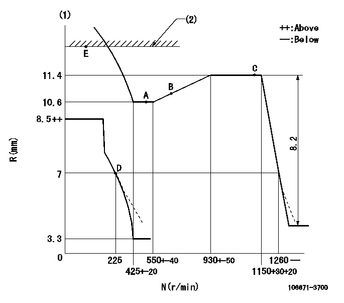
N:Pump speed
R:Rack position (mm)
(1)Beginning of damper spring operation: DL
(2)RACK LIMIT
----------
DL=6.2-0.2mm
----------
----------
DL=6.2-0.2mm
----------
Speed control lever angle

F:Full speed
----------
----------
a=3deg+-5deg
----------
----------
a=3deg+-5deg
0000000901

F:Full load
I:Idle
(1)Stopper bolt setting
----------
----------
a=15deg+-5deg b=27.5deg+-3deg
----------
----------
a=15deg+-5deg b=27.5deg+-3deg
Stop lever angle
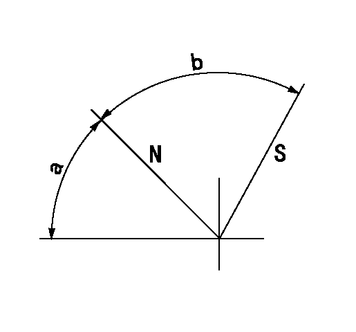
N:Pump normal
S:Stop the pump.
----------
----------
a=45deg+-5deg b=64deg+-5deg
----------
----------
a=45deg+-5deg b=64deg+-5deg
0000001501 GOVERNOR TORQUE CONTROL

Dr:Torque control stroke
(A): Without torque control spring capsule
1. Adjustment procedures
(1)Procedure is the same as that for the RFD (former type), except that the positive torque control stroke must be determined at the full lever setting.
2. Procedures for adjustment
(1)Remove the torque control spring capsule.
(2)Operate the pump at approximately N1. (End of idling spring operation < N1.)
(3)Tilt the lever to the full side.
(4)Set so that R = RF.
(5)Increase the speed by pushing in the screw (attached to the bracket on the rear of the tension lever) through the adjusting window.
(6)Adjust so that the torque control stroke Dr1 can be obtained.
(7)Align N2 and N3 with the torque control spring capsule.
3. Final confirmation
(1)After final confirmation, temporarily set the load lever to N = N1, R = idling position.
(2)From this condition, increase speed to N = N4.
(3)Confirm that positive torque control stroke is Dr2.
----------
N1=500r/min N2=550+-40r/min N3=930+-50r/min N4=1000r/min RF=10.6mm Dr1=0.8mm Dr2=0+0.3mm
----------
----------
N1=500r/min N2=550+-40r/min N3=930+-50r/min N4=1000r/min RF=10.6mm Dr1=0.8mm Dr2=0+0.3mm
----------
Information:
350 hp (261 kW) at 2100 rpm and Above (Includes all higher hp [kW] ratings)
Use fuel consumption, distance (odometer) interval or service hours, whichever occurs first.Daily
Engine Crankcase - Check oil level Leaks and Loose Connections - Inspect Engine Cooling System - Check coolant level Air Cleaner Indicator (If Equipped) - Check Air-to-Air Aftercooler System - CheckPM Level 1
Every 12,500 Miles (20 000 km) or 2500 gal (9500 L) of Fuel or 250 Hours*
Scheduled Oil Sampling (S O S) - Obtain Engine Oil and Filter(s) (NOTE A) - Replace Fuel Filters - Replace final filter/Clean primary filter (if equipped) Cooling System - Test for coolant additive concentration Crankcase Breather - Clean Alternator, Fan and Accessory Drive Belts - Inspect Hoses and Clamps - Inspect/Replace Air-to-Air Aftercooler System - Inspect/Check Fan Drive Bearing - Lubricate Valve Lash (at First PM 1 Interval Only) - Check/AdjustPM Level 2
Every 166,000 Miles (267 000 km) or 33,300 gal (126 000 L) of Fuel or 3,330 Hours*
Performance Analysis Report (PAR) - Obtain Engine - Steam clean Turbocharger - Inspect/Check Engine Mounts - Inspect/Check Vibration Damper - Inspect/Check Air Compressor - Inspect/Check Thermostat - Replace Cooling System - Clean/Flush Water Pump - Rebuild or Exchang2PM Level 3
Every 250,000 Miles (400 000 km) or 50,000 gal (190 000 L) of Fuel or 5,000 Hours*
Fuel Injection Nozzles - Exchange2 Air Compressor - Rebuild or Exchange2 Turbocharger - Rebuild or Exchange2 Valve Lash and Valve Rotators - Check/Adjust Rack Position, Timing Position and Throttle Position Sensor Calibration - Check/Adjust Crankshaft Bearings - Inspect/ReplaceOverhaul
Every 500,000 Miles (800 000 km) or 100,000 gal (380 000 L) of Fuel or 10,000 Hours
Overhaul Before Failure (In-Frame Overhaul) Cylinder Head Assembly, Cylinder Packs, Oil Pump and Fuel Transfer Pump - Rebuild or Exchange2 Main and Connecting Rod Bearings - Replace Crankshaft - Inspect Camshaft - Inspect Camshaft Followers - Inspect Damper - Inspect Spacer Plate - Inspect Oil Cooler Core - Clean/Test Air-to-Air Aftercooler Core - Clean/Test After Failure Overhaul (Out-of-Frame Overhaul)*First Perform Previous Service Hour ItemsThe distance (odometer) intervals shown on this schedule are based on average fuel rates. This chart assumes 5 mpg (2.1 km/L). Your distance maintenance intervals may need to be adjusted if actual fuel consumption differs from the average fuel consumption Caterpillar considered.Example: Your 3406B rated 425 hp (317 KW) at 2100 rpm is averaging 4.5 mpg (1.9 km/L) due to high load factor operation. The engine consumes 2500 gallons (9500 L) of fuel to travel 11,250 miles (18 000 km). PM Level 1 should be performed at every 11,250 miles (18 000 km) instead of 12,500 miles (20 000 km) shown on the schedule.1Experience has shown that maintenance intervals are most accurately scheuled on the basis of fuel consumed. Rated engine speed and load factor are also important for some components. However, Caterpillar recognizes that the distance (odometer) interval is most commonly used to schedule maintenance for on-highway vehicles. A: Remote mounted or auxiliary filters require additional oil. A 13 quart (12.3 L) supplemental oil filtration system