Information injection-pump assembly
BOSCH
9 400 616 777
9400616777
ZEXEL
106671-3680
1066713680
HINO
220004320A
220004320a

Rating:
Service parts 106671-3680 INJECTION-PUMP ASSEMBLY:
1.
_
7.
COUPLING PLATE
8.
_
9.
_
11.
Nozzle and Holder
23600-1221A
12.
Open Pre:MPa(Kqf/cm2)
21.6{220}

15.
NOZZLE SET
Include in #1:
106671-3680
as INJECTION-PUMP ASSEMBLY
Cross reference number
BOSCH
9 400 616 777
9400616777
ZEXEL
106671-3680
1066713680
HINO
220004320A
220004320a
Zexel num
Bosch num
Firm num
Name
106671-3680
9 400 616 777
220004320A HINO
INJECTION-PUMP ASSEMBLY
EK100 * K 14CA PE6P,6PD PE
EK100 * K 14CA PE6P,6PD PE
Calibration Data:
Adjustment conditions
Test oil
1404 Test oil ISO4113 or {SAEJ967d}
1404 Test oil ISO4113 or {SAEJ967d}
Test oil temperature
degC
40
40
45
Nozzle and nozzle holder
105780-8140
Bosch type code
EF8511/9A
Nozzle
105780-0000
Bosch type code
DN12SD12T
Nozzle holder
105780-2080
Bosch type code
EF8511/9
Opening pressure
MPa
17.2
Opening pressure
kgf/cm2
175
Injection pipe
Outer diameter - inner diameter - length (mm) mm 8-3-600
Outer diameter - inner diameter - length (mm) mm 8-3-600
Overflow valve
134424-0920
Overflow valve opening pressure
kPa
162
147
177
Overflow valve opening pressure
kgf/cm2
1.65
1.5
1.8
Tester oil delivery pressure
kPa
157
157
157
Tester oil delivery pressure
kgf/cm2
1.6
1.6
1.6
Direction of rotation (viewed from drive side)
Left L
Left L
Injection timing adjustment
Direction of rotation (viewed from drive side)
Left L
Left L
Injection order
1-4-2-6-
3-5
Pre-stroke
mm
3.3
3.24
3.3
Beginning of injection position
Drive side NO.1
Drive side NO.1
Difference between angles 1
Cal 1-4 deg. 60 59.75 60.25
Cal 1-4 deg. 60 59.75 60.25
Difference between angles 2
Cyl.1-2 deg. 120 119.75 120.25
Cyl.1-2 deg. 120 119.75 120.25
Difference between angles 3
Cal 1-6 deg. 180 179.75 180.25
Cal 1-6 deg. 180 179.75 180.25
Difference between angles 4
Cal 1-3 deg. 240 239.75 240.25
Cal 1-3 deg. 240 239.75 240.25
Difference between angles 5
Cal 1-5 deg. 300 299.75 300.25
Cal 1-5 deg. 300 299.75 300.25
Injection quantity adjustment
Adjusting point
A
Rack position
10.6
Pump speed
r/min
500
500
500
Average injection quantity
mm3/st.
129
126
132
Max. variation between cylinders
%
0
-4
4
Fixing the lever
*
Injection quantity adjustment_02
Adjusting point
B
Rack position
10.9
Pump speed
r/min
700
700
700
Average injection quantity
mm3/st.
139.5
137.5
141.5
Max. variation between cylinders
%
0
-2
2
Basic
*
Fixing the lever
*
Injection quantity adjustment_03
Adjusting point
C
Rack position
11.4
Pump speed
r/min
1150
1150
1150
Average injection quantity
mm3/st.
148
145
151
Max. variation between cylinders
%
0
-4
4
Fixing the lever
*
Injection quantity adjustment_04
Adjusting point
D
Rack position
7+-0.5
Pump speed
r/min
225
225
225
Average injection quantity
mm3/st.
15
12
18
Max. variation between cylinders
%
0
-15
15
Fixing the rack
*
Injection quantity adjustment_05
Adjusting point
E
Rack position
-
Pump speed
r/min
100
100
100
Average injection quantity
mm3/st.
126.3
119.3
133.3
Fixing the lever
*
Timer adjustment
Pump speed
r/min
1000--
Advance angle
deg.
0
0
0
Remarks
Start
Start
Timer adjustment_02
Pump speed
r/min
950
Advance angle
deg.
0.5
Timer adjustment_03
Pump speed
r/min
1000
Advance angle
deg.
1.5
Timer adjustment_04
Pump speed
r/min
1050
Advance angle
deg.
1.9
1.4
2.4
Timer adjustment_05
Pump speed
r/min
1150
Advance angle
deg.
4.5
4.2
4.8
Remarks
Finish
Finish
Test data Ex:
Governor adjustment
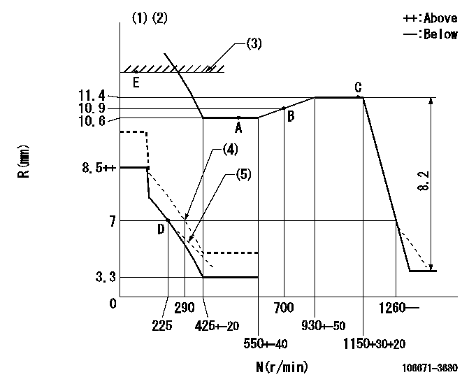
N:Pump speed
R:Rack position (mm)
(1)Lever ratio: RT
(2)Target shim dimension: TH
(3)RACK LIMIT
(4)Set to idle at shipping.
(5)Damper spring setting: DL
----------
RT=1 TH=2mm DL=6.2-0.2mm
----------
----------
RT=1 TH=2mm DL=6.2-0.2mm
----------
Speed control lever angle

F:Full speed
----------
----------
a=3deg+-5deg
----------
----------
a=3deg+-5deg
0000000901
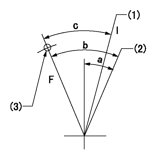
F:Full load
I:Idle
(1)At shipping
(2)Set point D
(3)Use the hole at R = aa
----------
aa=58mm
----------
a=10deg+-5deg b=27.5deg+-3deg c=24deg+-5deg
----------
aa=58mm
----------
a=10deg+-5deg b=27.5deg+-3deg c=24deg+-5deg
Stop lever angle

N:Pump normal
S:Stop the pump.
----------
----------
a=15deg+-5deg b=64deg+-5deg
----------
----------
a=15deg+-5deg b=64deg+-5deg
0000001501 GOVERNOR TORQUE CONTROL

Dr:Torque control stroke
(A): Without torque control spring capsule
1. Adjustment procedures
(1)Procedure is the same as that for the RFD (former type), except that the positive torque control stroke must be determined at the full lever setting.
2. Procedures for adjustment
(1)Remove the torque control spring capsule.
(2)Operate the pump at approximately N1. (End of idling spring operation < N1.)
(3)Tilt the lever to the full side.
(4)Set so that R = RF.
(5)Increase the speed by pushing in the screw (attached to the bracket on the rear of the tension lever) through the adjusting window.
(6)Adjust so that the torque control stroke Dr1 can be obtained.
(7)Align N2 and N3 with the torque control spring capsule.
3. Final confirmation
(1)After final confirmation, temporarily set the load lever to N = N1, R = idling position.
(2)From this condition, increase speed to N = N4.
(3)Confirm that positive torque control stroke is Dr2.
----------
N1=500r/min N2=550+-40r/min N3=930+-50r/min N4=1000r/min RF=10.6mm Dr1=0.8mm Dr2=0+0.3mm
----------
----------
N1=500r/min N2=550+-40r/min N3=930+-50r/min N4=1000r/min RF=10.6mm Dr1=0.8mm Dr2=0+0.3mm
----------
Information:
Table 1
Revision Summary of Changes
01 Title updated. Effectivity and reference added. Changes were made in problem and solution section. Introduction
The problem that is identified below does not have a known permanent solution. Until a permanent solution is known, use the solution that is identified below.Problem
Illustration 1 g06583948
Clogged diesel particulate filter
Reports have been received that the Diesel Particulate Filter (DPF) may clog at less than 300 hours on the machines listed above. The insulation from the Diesel Oxidation Catalyst (DOC) causes clogging of the DPF.These additional related problems may occur:
Diagnostic code 523602-0"Aftertreatment Regeneration Frequency" may occur
Erratic soot levels
Fuel dilution of the oil or poor oil quality at low machine hoursSolution
Do not operate or work on this product unless you have read and understood the instruction and warnings in the relevant Operation and Maintenance Manuals and relevant service literature. Failure to follow the instructions or heed the warnings could result in injury or death. Proper care is your responsibility.
In the event of failure, follow the troubleshooting procedure below:Troubleshooting Procedure
Check the fuel/water separator for water.Note: Water in fuel can cause excessive ash buildup in the DPF.
Check the air filter and replace the air filter if necessary.
Check the engine oil level and look for fuel dilution of engine oil. Replace the engine oil and filter if fuel dilution has occurred.Note: Frequent regeneration may cause fuel dilution of engine oil due to the fuel dosing required for regeneration. A failed injector could also cause fuel dilution of engine oil.
Check the coolant level.
Troubleshoot active diagnostic codes. Refer to Troubleshooting, UENR3390 on how to troubleshoot excessive DPF regeneration.
Complete a parked DPF regeneration to remove soot.
Inspect the differential pressure sensor tubes for damage.
Inspect the differential pressure sensor tubes and sensors for debris.
Bring the engine up to operating temperature and complete a fuel injector cut-out test to test for failed injectors.If the problem exists even after performing the troubleshooting procedure, create a Global Dealer Solution Network (GDSN) Product Health Service Request (SR) with Workgroup / Subsystem of “Base Machine”. Attach any pertinent photos and detailed failure information for the product group. Mention the CPI number 471218 in the CPI field (and /or) the Technical Information Bulletin (TIB) media number (M0121625) in the description prior to submitting to Caterpillar.Additional troubleshooting/documentation may include:
A photo of the DPF and DOC for identification information
An inspection of the face of the DPF for fibrous material
An inspection of engine oil sample
An inspection of the fuel sample if needed based on diagnostic codes
Have questions with 106671-3680?
Group cross 106671-3680 ZEXEL
Hino
106671-3680
9 400 616 777
220004320A
INJECTION-PUMP ASSEMBLY
EK100
EK100