Information injection-pump assembly
ZEXEL
106671-3631
1066713631
HINO
220201920A
220201920a

Rating:
Cross reference number
ZEXEL
106671-3631
1066713631
HINO
220201920A
220201920a
Zexel num
Bosch num
Firm num
Name
106671-3631
220201920A HINO
INJECTION-PUMP ASSEMBLY
EP100 *
EP100 *
Calibration Data:
Adjustment conditions
Test oil
1404 Test oil ISO4113 or {SAEJ967d}
1404 Test oil ISO4113 or {SAEJ967d}
Test oil temperature
degC
40
40
45
Nozzle and nozzle holder
105780-8140
Bosch type code
EF8511/9A
Nozzle
105780-0000
Bosch type code
DN12SD12T
Nozzle holder
105780-2080
Bosch type code
EF8511/9
Opening pressure
MPa
17.2
Opening pressure
kgf/cm2
175
Injection pipe
Outer diameter - inner diameter - length (mm) mm 8-3-600
Outer diameter - inner diameter - length (mm) mm 8-3-600
Overflow valve opening pressure
kPa
162
147
177
Overflow valve opening pressure
kgf/cm2
1.65
1.5
1.8
Tester oil delivery pressure
kPa
157
157
157
Tester oil delivery pressure
kgf/cm2
1.6
1.6
1.6
Direction of rotation (viewed from drive side)
Right R
Right R
Injection timing adjustment
Direction of rotation (viewed from drive side)
Right R
Right R
Injection order
1-4-2-6-
3-5
Pre-stroke
mm
4.5
4.4
4.5
Beginning of injection position
Drive side NO.1
Drive side NO.1
Difference between angles 1
Cal 1-4 deg. 60 59.5 60.5
Cal 1-4 deg. 60 59.5 60.5
Difference between angles 2
Cyl.1-2 deg. 120 119.5 120.5
Cyl.1-2 deg. 120 119.5 120.5
Difference between angles 3
Cal 1-6 deg. 180 179.5 180.5
Cal 1-6 deg. 180 179.5 180.5
Difference between angles 4
Cal 1-3 deg. 240 239.5 240.5
Cal 1-3 deg. 240 239.5 240.5
Difference between angles 5
Cal 1-5 deg. 300 299.5 300.5
Cal 1-5 deg. 300 299.5 300.5
Injection quantity adjustment
Adjusting point
A
Rack position
8.1
Pump speed
r/min
700
700
700
Average injection quantity
mm3/st.
119.4
117.4
121.4
Max. variation between cylinders
%
0
-2
2
Basic
*
Fixing the lever
*
Injection quantity adjustment_02
Adjusting point
B
Rack position
5.4+-0.5
Pump speed
r/min
275
275
275
Average injection quantity
mm3/st.
12
9
15
Max. variation between cylinders
%
0
-15
15
Fixing the rack
*
Injection quantity adjustment_03
Adjusting point
C
Rack position
10.1+-0.
5
Pump speed
r/min
100
100
100
Average injection quantity
mm3/st.
138
133
143
Fixing the lever
*
Rack limit
*
Timer adjustment
Pump speed
r/min
975--
Advance angle
deg.
0
0
0
Remarks
Start
Start
Timer adjustment_02
Pump speed
r/min
925
Advance angle
deg.
0.3
Timer adjustment_03
Pump speed
r/min
1050
Advance angle
deg.
1.3
0.8
1.8
Timer adjustment_04
Pump speed
r/min
1150
Advance angle
deg.
2.5
2.2
2.8
Remarks
Finish
Finish
Test data Ex:
Governor adjustment
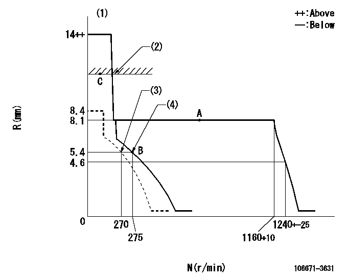
N:Pump speed
R:Rack position (mm)
(1)Target notch: K
(2)RACK LIMIT
(3)Set idle sub-spring
(4)Main spring setting
----------
K=10
----------
----------
K=10
----------
Speed control lever angle
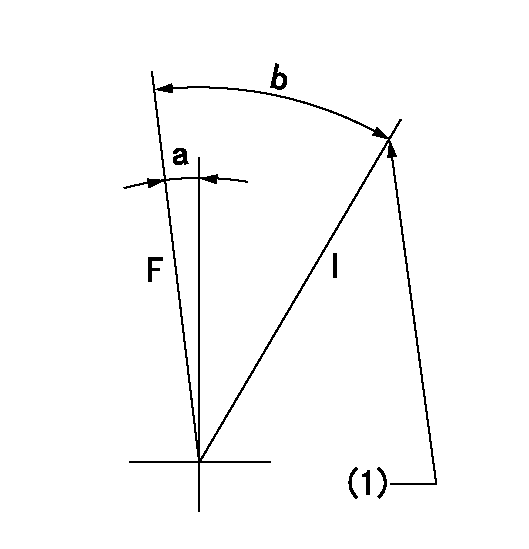
F:Full speed
I:Idle
(1)Stopper bolt setting
----------
----------
a=(9deg)+-5deg b=(30deg)+-5deg
----------
----------
a=(9deg)+-5deg b=(30deg)+-5deg
Stop lever angle

N:Pump normal
S:Stop the pump.
----------
----------
a=27deg+-5deg b=53deg+-5deg
----------
----------
a=27deg+-5deg b=53deg+-5deg
0000001501 Q ADJUSTMENT PIPING
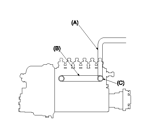
Tester fuel pipe A
Adjust screw A so that the timer advance angle determined in (B) can be obtained.
Fuel inlet C
Piping at standard injection quantity adjustment
1. Because the pump gallery is divided into two, be careful of the fuel piping at adjustment.
----------
----------
----------
----------
Timing setting

(1)Pump vertical direction
(2)Coupling's key groove position at No 1 cylinder's beginning of injection
(3)-
(4)-
----------
----------
a=(40deg)
----------
----------
a=(40deg)
Information:
Until recently, engine maintenance and repair management involved changing the oil when it was convenient and repairing the engine when it was damaged. This seemed to be the accepted way of managing a maintenance operation.However, due to a variety of circumstances, freight hauling jobs became increasingly competitive. This competitiveness caused users to look for ways to prolong equipment life and lower operating costs so that they could be competitive when bidding jobs.To assist Caterpillar Truck Engine users in prolonging engine life and reducing operating costs, the Value Planned Repair approach to engine maintenance was developed.The Value Planned Repair approach can be tailored for any engine. This approach, when properly structured, outlines every maintenance and repair service required to support an engine from the day it enters service until the day it is retired.To ensure the repair is performed efficiently and expediently, the Value Planned Repair concept approaches a given repair in three basic steps: 1. Repair determination2. Evaluation of repair options3. Selection of the most appropriate optionThe Value Planned Repair approach addresses: * Services required to maintain an engine at optimum efficiency.* Scheduled maintenance, repairs and overhauls to minimize unscheduled downtime.* Preplanned repairs and overhauls that can be flatrated, putting you in charge of costs.* Repair or overhaul options designed to restore the engine to proper operating condition.* Repair or overhaul options designed to renew the engine if a failure has occurred.Part of the Value Planned Repair approach is the repair before failure concept. The objective of the repair before failure concept is to repair the engine before a failure takes place. The fact that a failure has not taken place makes the repair before failure concept more economical since a high degree of parts such as pistons, liners, valves, etc., and major castings such as cylinder blocks, cylinder heads, etc., can be reused.Also, an extensive internal cleaning of the engine, which is labor intensive, is eliminated because a debris-generating failure has not taken place.The best part of the repair before failure concept is that unscheduled downtime is minimized and in most cases eliminated.Because the repair or overhaul can be scheduled, it allows the user to adjust his operation accordingly.The overall benefit to a customer who repairs an engine before failure is that the customer and not the engine is in control of the repairs required.To stress the importance of the Value Planned Repair approach, please consider the following example that reflects the difference in the cost of a before failure repair versus the cost of an after failure repair.The cost to repair a turbocharger after it fails is approximately five times more than the cost of repairing a turbocharger before it fails.However, if parts from a damaged turbocharger enters the engine, then the cost to repair your engine could be as high as 10 times or more the cost of repairing a turbocharger before it fails.By subscribing to the Value Planned Repair approach, you can avoid spending money on costly repairs that should have been prevented.Caterpillar strongly
Have questions with 106671-3631?
Group cross 106671-3631 ZEXEL
Hino
106671-3631
220201920A
INJECTION-PUMP ASSEMBLY
EP100
EP100